What does a marking like II 1/2 G or Ga/Gb mean?
Abstract
It marks equipment built to sit across a zone boundary: one part suits Zone 0 (category 1, EPL Ga), the rest Zone 1 (category 2, EPL Gb), with a separation element between them, as with a level sensor in a tank wall. The whole device may not go into Zone 0.
A marking such as II 1/2 G (ATEX) or Ga/Gb (EPL) identifies equipment designed to be mounted across a zone boundary: one part is suitable for the more hazardous side, here Zone 0 (category 1, EPL Ga), the rest for Zone 1 (category 2, EPL Gb), with a separation element between them. The classic example is a level sensor or gauge fitted through the wall or roof of a tank whose vapour space is Zone 0 while the outside is Zone 1. It does not mean the whole device may be installed in Zone 0.
Short answer
- Two levels in one item. The slash separates the category or EPL for one part from that for the other part of the same equipment.
- The European Commission's ATEX Guidelines give
II 1/2 Gas equipment installed with one part in Zone 0 and one part in Zone 1, and name a level gauge in a tank wall between Zone 0 and Zone 1 as the typical example.II 2/3 Gis the same idea between Zone 1 and Zone 2. - IEC 60079-26 (edition 4, 2021) sets the construction, testing and marking rules for equipment with parts of different EPLs and a separation element, for gas, dust and mixed boundaries.
- The separation element is the safety-critical part: a partition wall, a sealed bushing, a joint or a ventilated gap, as allowed by the standard. Its wall thickness must be stated in the instructions.
- Install it exactly as the instructions say: which part faces the process, which wall or flange, and what may not be changed.
How the boundary equipment works
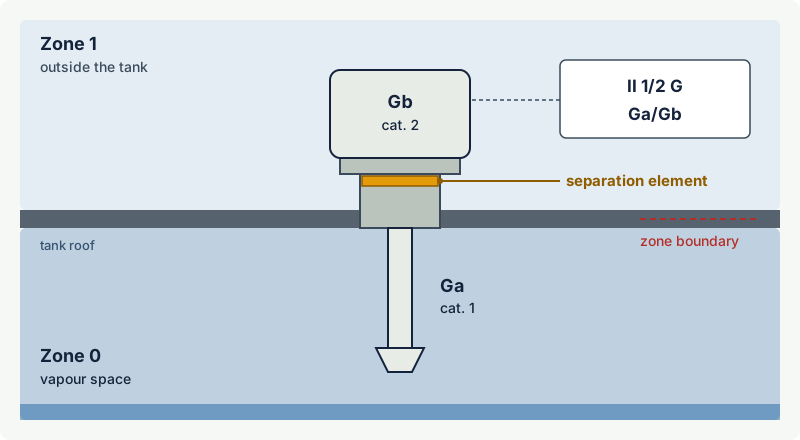
The part inside the tank meets the requirements for EPL Ga: it must not become an ignition source even with rare faults. Typically this is intrinsically safe circuitry at level ia or a passive sensing element. The housing outside only needs EPL Gb, so it may use a flameproof or increased-safety enclosure with electronics and terminals.
The separation element keeps the two worlds apart. IEC 60079-26 describes several constructions, including a mechanical partition wall, a metallic partition with gas-tight conductor bushings, a partition supplemented by a joint, and a partition supplemented by natural ventilation. Its tables give the allowed constructions for each boundary: Zone 0 to Zone 1, Zone 1 to Zone 2, the dust zones and gas next to dust. The 2021 edition requires the partition wall thickness to be stated in the instructions and adds warnings where the element is exposed to abrasive dust flow, because corrosion or erosion of a thin wall can quietly remove the protection.
Note: The slash marking is different from Ga achieved by combining two independent types of protection, each at EPL Gb. IEC 60079-26 allows that route too; such equipment is marked plain Ga and may be installed entirely in Zone 0, within its certificate.
Practical case: a radar level transmitter on a solvent tank
An instrument engineer must select a level transmitter for a fixed-roof tank storing toluene. The area classification gives Zone 0 inside the tank above the liquid and Zone 1 in a sphere around the roof nozzle. The candidate is marked II 1/2 G Ex ia/db IIB T4 Ga/Gb (illustrative).
The engineer checks:
- Boundary. The antenna is inside the tank (Zone 0, Ga); the housing is outside on the roof nozzle (Zone 1, Gb). That matches the marking.
- Gas group and temperature class. IIB and T4 cover toluene (IIA, T1 in the excodex library).
- Separation element limits. The instructions state the process temperature and pressure range, the materials in contact with the process, and the minimum wall thickness. They must suit the tank, including corrosion.
- Mounting. The process connection must be the one specified, and the housing must not be rotated or dismantled in a way that disturbs the separation element.
- Inspection. The register notes the separation element as an inspection item, with any corrosion or abrasion warning from the instructions.
A transmitter marked only II 2 G ... Gb would not be acceptable here, because its antenna would sit in Zone 0.
Common mistakes
- Reading
1/2as "category 1 or 2, installer's choice". Each part has its own fixed category. - Installing the device the wrong way round or with the housing inside the vessel.
- Ignoring the process limits on the separation element (temperature, pressure, corrosion) because the Ex marking looks right.
- Treating
Ga/Gbas a Zone 0 rating for the whole device.
Related on excodex
- ATEX equipment categories 1, 2 and 3 and how they relate to EPLs
- Equipment Protection Levels (EPL): Ga, Gb, Gc, Da, Db, Dc and how they match zones
- [What do brackets mean in markings such as [Ex ia] or II (1) G?](/article/1350)
- Which protection concepts can be used in Zone 0?
- Tool: Ex marking check; standards space IEC 60079-26
Standards and further reading
- IEC 60079-26:2021 (edition 4), equipment with separation elements or combined levels of protection: scope, separation element types and changes from the 2014 edition, shown in the publisher's preview: vde-verlag.de (PDF)
- European Commission, ATEX 2014/34/EU Guidelines, 6th edition (January 2026), Table 4 and Table 7 on equipment with different categories: single-market-economy.ec.europa.eu (PDF)
- IEC TS 60079-40, process sealing between flammable process fluids and electrical systems.
This article is general technical information prepared by the excodex editorial team. It does not replace the applicable standards, the equipment certificates and instructions, national regulations or the assessment of a competent person.