What is the difference between explosion suppression and explosion isolation?
Abstract
Suppression detects an explosion in its first milliseconds and extinguishes it inside the protected vessel. Isolation stops flame, and in some designs pressure, from travelling through ducts into connected equipment. A vessel with open connections usually needs isolation too.
Explosion suppression protects the vessel in which the explosion starts; explosion isolation protects everything connected to it. A suppression system detects an incipient explosion and fills the enclosure with suppressant within milliseconds, so the explosion is extinguished inside at a low pressure. An isolation system acts in the ducts, pipes, chutes and conveyors and stops the flame, and in some designs the pressure wave, from travelling into the next vessel or into the building.
Short answer
- Where it acts: suppression inside the enclosure (filter, mill, dryer, silo); isolation in the connections between enclosures.
- What it achieves: suppression keeps the explosion pressure in the vessel low and prevents a fireball outside it; isolation prevents propagation, flame jet ignition and pressure piling in connected plant.
- Neither replaces the other. A suppressed or vented vessel still pushes pressure and flame into its open connections, and an isolation device does nothing for the vessel it is fitted to.
- They can share hardware. A chemical isolation barrier (extinguishing barrier) uses the same detectors and suppressant containers as a suppression system, but fires them into a duct to stop the flame front, not to protect a vessel.
- Standards: in Europe EN 14373 covers suppression and EN 15089 covers isolation; in North America NFPA 69 treats them in separate chapters. Both are protective systems under Directive 2014/34/EU.
How explosion suppression works
A suppression system has three parts: explosion detectors (fast pressure sensors or optical sensors), a control and indicating unit, and one or more high rate discharge (HRD) suppressors, pressurised containers that open within milliseconds. When the detector sees the first pressure rise or flame, the control unit fires the suppressors and the suppressant, commonly a dry powder similar to those used in fire extinguishers and in some cases water, is spread through the enclosure and quenches the flame while it is still small.
The pressure stays far below that of an unprotected explosion, and nothing leaves the vessel, which must still withstand the reduced pressure stated in the design. EN 14373 sets the design requirements and test methods, including scale-up from test vessels to larger volumes. Suppression suits indoor equipment that cannot be vented safely, toxic products and vessels too weak or complex for venting.
How explosion isolation works
When an explosion starts in one vessel, the expanding gas drives flame and pressure into every open connection. A flame that runs along a duct speeds up and arrives at the next vessel as a turbulent jet, often into dust that the pressure wave has already stirred up and compressed. The second explosion can be far more violent than the first. EN 15089 describes isolation as a protective measure that prevents flame and pressure, or flame only, from passing through connecting pipes or ducts, and distinguishes:
| Type | How it works | Examples |
|---|---|---|
| Active isolation | A detector and control unit trigger a device | Fast-acting isolation valve (slide gate or pinch valve), extinguishing barrier that injects suppressant into the duct |
| Passive isolation | Works without detectors or a control unit | Isolation flap valve closed by the pressure wave, rotary valve proven as a flame barrier, product choke such as a screw with a missing flight or a hopper kept above a minimum level |
| Complete isolation | Stops flame and pressure | Fast-acting isolation valve, interlocked double valve arrangement, closed flap valve |
| Partial isolation | Stops the flame only, the pressure wave passes | Extinguishing barrier, rotary valve |
HSE guidance adds a point that is easy to miss: elevators, conveyors and rotary valves should be stopped automatically when an explosion is detected, for example by switches on the vent panels, because running equipment keeps moving burning material through the plant. EN 15089 also notes that isolation does not generally stop smouldering or burning powder from being carried further, so that risk needs its own assessment.
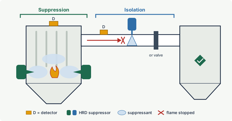
Practical case: the same hardware, two different jobs
An indoor dust collector serves a mill and three sanding machines. It is protected by suppression: detectors and two HRD suppressors on the dirty side. The inlet duct gets a chemical barrier: one detector in the duct near the collector and one HRD suppressor further along it, positioned according to the certified installation distances so that suppressant fills the duct before the flame front arrives. The hopper outlet gets a rotary valve certified as an isolation device, which stops on detection.
The hardware may be the same, but each part has its own design basis. The suppression design depends on the collector volume, its strength and the Kst and Pmax of the collected dust. The barrier design depends on the duct diameter, the air velocity, the distance from the collector and the direction in which a flame can travel. Changing the duct layout or the fan therefore requires a review of the isolation, even when the collector itself is unchanged.
The 2012 flash fire in East Rutherford, New Jersey shows why both are needed. According to the US Chemical Safety Board (CSB), suppression equipment contained an explosion in a rooftop dust collector, but the pressure reversed the airflow back through the ducts into the pre-mix room, where a flash fire burned seven workers.
Common mistakes
- "The collector has suppression, so the ducts are covered." Suppression keeps the explosion pressure in the vessel low, but it does not stop flame or pressure from entering the connections.
- Treating a partial isolation device as a pressure barrier. A chemical barrier stops the flame, but the pressure wave passes; the downstream equipment must tolerate that pressure.
- Moving a barrier or valve outside its certified distance range. Isolation works only within the distances, duct sizes, flow velocities and dusts stated in its certificate and instructions.
Related on excodex
- Dust explosion protection: venting, suppression, isolation and containment
- Why does a vented dust collector still need isolation on the inlet duct?
- How often must explosion vents and suppression systems be inspected?
- Should a dust collector be located inside or outside a building?
- Standards space: ATEX 2014/34/EU
Standards and further reading
- EN 14373:2021+A1:2025, explosion suppression systems (design, effectiveness testing, calculation models for scale-up, installation, commissioning and maintenance instructions): sample pages
- EN 15089:2009, explosion isolation systems (active and passive, complete and partial isolation, effectiveness testing): sample pages
- NFPA 69, standard on explosion prevention systems (deflagration suppression, active and passive isolation).
- Directive 2014/34/EU, Article 2, definition of protective systems: legislation.gov.uk
- HSE, HSG103 Safe handling of combustible dusts (suppression, isolation methods, shutdown of conveying equipment): hse.gov.uk (PDF)
- US Chemical Safety Board, 2012 East Rutherford flash fire investigation: csb.gov
This article is general technical information prepared by the excodex editorial team. It does not replace the applicable standards, the equipment certificates and instructions, national regulations or the assessment of a competent person.