Dust explosion protection: venting, suppression, isolation and containment
Abstract
When a dust explosion inside plant cannot be ruled out, its effects are limited by containment, venting, flameless venting or suppression, plus isolation of connected ducts. How each works, the design data (Kst, Pmax, Pstat, Pred), a vent sizing example and what to inspect.
Dust explosion protection accepts that an explosion may start inside a piece of plant and makes sure it does no harm. Four techniques do this: containment (the equipment is strong enough to withstand the explosion pressure), venting (a weak panel opens early and releases the explosion to a safe place, or through a flameless device where open discharge is unsafe), suppression (the explosion is detected in its first milliseconds and extinguished by injected suppressant) and isolation (flame and pressure are stopped from travelling through ducts, chutes and conveyors into connected equipment). Containment, venting and suppression protect the vessel itself; isolation is needed in addition wherever that vessel is connected to others.
This article explains how each technique works, which data it needs, a worked vent sizing example with the EN 14491 method, how to choose a protection concept and what to inspect.
Key points
- Protective measures limit the effects of an explosion; they do not stop one from starting. They are used together with ignition source control, never as a replacement for it.
- A confined dust cloud typically reaches 8 to 10 bar when it explodes (HSE guidance). Ordinary filters, silos and ducts fail at a small fraction of that, which is why unprotected plant bursts.
- Venting is designed from the vessel volume and shape, the dust's Kst and Pmax, the vent opening pressure Pstat and the reduced explosion pressure Pred, which must stay below the pressure the vessel can withstand. EN 14491 and NFPA 68 give the methods; their equations differ.
- An open vent releases a fireball and a pressure wave. Vents must discharge to a safe place, usually outdoors, or use a flameless venting device certified for the dust.
- Suppression systems detect the explosion within milliseconds and fill the vessel with suppressant, so nothing burns outside it. They suit indoor equipment and toxic products.
- Isolation is needed on every connection through which an explosion can travel. Without it, a protected vessel can still pass a flame jet into the next vessel, a pattern seen in several investigated incidents.
- Under Directive 2014/34/EU, devices placed on the market separately to halt incipient explosions or limit their range are protective systems, assessed by EU-type examination or unit verification.
Prevention first, protection as the backstop
Explosion safety follows a fixed order, set out in EN 1127-1 and in the ATEX workplace directive 1999/92/EC: first avoid the explosive atmosphere, then avoid effective ignition sources, and only where an explosion still cannot be excluded, limit its effects to a safe level. The third step is often called constructive or design protection, because it is built into the plant.
Inside many dust handling machines the first two steps cannot be achieved with certainty. A dust collector, a mill or a silo during filling contains an explosive cloud in normal operation (Zone 20), and ignition sources such as tramp metal, friction, smouldering particles from upstream or electrostatic discharges can be reduced but rarely excluded. Inerting, which removes enough oxygen to make the cloud non-explosive, is a prevention measure and an alternative for some processes; see Oxygen concentration, enrichment and inerting.
| Technique | Principle | What leaves the vessel | Typical applications | Main standards |
|---|---|---|---|---|
| Containment | Vessel withstands the full explosion pressure | Nothing (if connections are isolated) | Small vessels, mills, vacuum-rated driers | EN 14460 |
| Venting | Weak panel opens and relieves pressure | Flame, burning and unburnt dust, pressure wave | Filters, cyclones, silos, bucket elevators outdoors or near an outside wall | EN 14491, NFPA 68, EN 14797 |
| Flameless venting | Vent plus a mesh that quenches flame and retains dust | Hot gas and a pressure wave, no flame | Indoor equipment where an open vent cannot discharge safely | EN 16009, NFPA 68 |
| Suppression | Detection and injection of suppressant | Nothing | Indoor and toxic or high-value processes, dryers, mills, mixers | EN 14373, NFPA 69 |
| Isolation | Barrier in ducts, chutes and conveyors | Nothing passes the barrier | Every connection between protected vessels | EN 15089, EN 16447, NFPA 69 |
Containment: explosion-resistant design
The simplest idea is to build the equipment strong enough. EN 14460 distinguishes two types:
- Explosion-pressure-resistant equipment withstands the explosion pressure without permanent deformation. It is designed much like a pressure vessel.
- Explosion-pressure-shock-resistant equipment may deform permanently, but must not rupture or create dangerous effects for its surroundings. This design was developed specifically for explosion protection and allows lighter construction, but the equipment must be inspected and possibly replaced after an event.
Containment works without any moving part, which makes it very reliable. Its limit is the pressure: HSE guidance notes that it is generally not practicable to build plant for 8 to 10 bar unless it is small and of simple circular or spherical shape. Hammer mills and some grinders are often strong enough by nature, and plant built to operate under vacuum may withstand the lower pressures of a dust explosion in it.
Three points are often overlooked:
- Everything must be strong enough. Doors, inspection hatches, flexible connections, sight glasses and the first sections of ducts must meet the same design pressure as the shell.
- Test values assume atmospheric pressure at ignition. Pmax is measured from an initial pressure of about 1 bar absolute; in pressurised equipment the explosion pressure rises roughly in proportion to the absolute starting pressure. EN 14460 covers starting pressures of 0.8 to 1.1 bar absolute.
- Containment still needs isolation. A contained explosion pushes flame and pressure into every open connection.
Containment is also combined with the other techniques: a vessel protected by venting or suppression only has to be designed for the reduced pressure Pred, not for Pmax.
Explosion venting
How a vent works
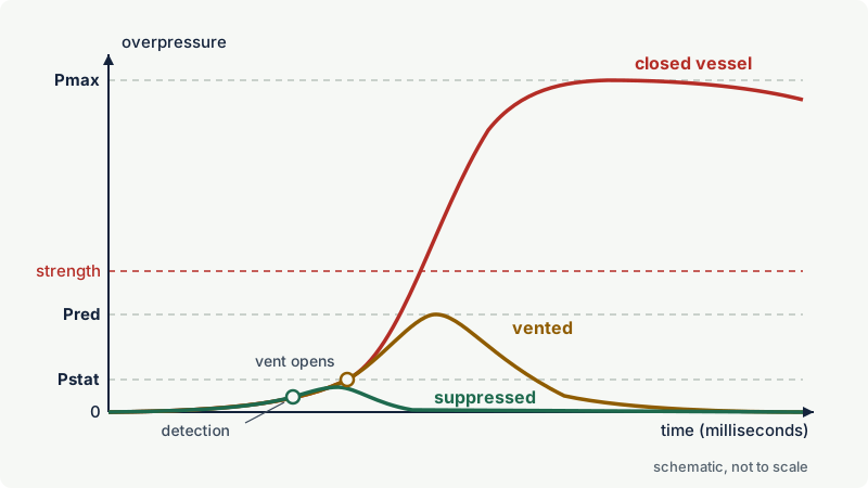
A vent is a deliberate weak point, a bursting panel or a hinged explosion door, sized so that it opens early and lets enough burnt and unburnt material out to keep the pressure inside below what the vessel can withstand. Two pressures define the design:
- Pstat, the static activation pressure: the overpressure at which the vent opens. It is set well below the vessel strength; lightweight panels often open at around 0.1 bar.
- Pred, the reduced explosion pressure: the highest pressure reached in the vented vessel. It must stay below the vessel's design strength, including all doors, flanges and connected parts.
Inputs for vent sizing
HSE guidance lists the minimum design inputs: the volume of the equipment, the dust properties measured in a 20 litre or larger test vessel, the strength of the plant and the opening pressure of the vent. The designer also needs the vessel shape (length to diameter ratio), the efficiency of the vent device, any vent duct and the process conditions. The dust data, Kst and Pmax, should come from a representative sample including fines; see Dust explosion parameters explained.
The sizing method in EN 14491 and NFPA 68
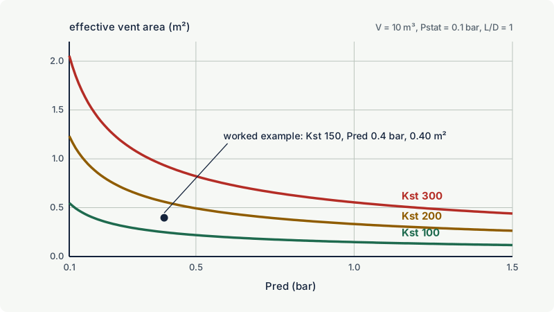
EN 14491 (current edition 2012) uses an empirical relationship for dust explosion venting of single enclosures that it shares with the German guideline VDI 3673 and with NFPA 68 editions before 2007. Since its 2007 edition NFPA 68 uses a different set of equations, so the two methods can give somewhat different vent areas for the same case; use one method consistently. For a compact vessel with a length to diameter ratio (L/D) of 1, the EN 14491 vent area A (m²) is:
A = [3.264 × 10⁻⁵ × Pmax × Kst × Pred^(-0.569) + 0.27 × (Pstat - 0.1) × Pred^(-0.5)] × V^0.753
with pressures in bar (overpressure), Kst in bar·m/s and V in m³. For elongated vessels (L/D from 1 to 20) the result is multiplied by a correction factor that grows with the logarithm of L/D and with lower Pred, so a tall silo needs much more vent area than a squat vessel of the same volume. A published summary of the 2012 method gives its range of validity: volumes from 0.1 to 10 000 m³, Pstat from 0.1 to 1 bar (a lower opening pressure is entered as 0.1 bar), Pred above 0.1 up to 2 bar, Pmax from 5 to 10 bar for Kst from 10 to 300 bar·m/s (5 to 12 bar for Kst from 300 to 800 bar·m/s), L/D up to 20, initial pressure close to atmospheric, normal air and temperatures from -20 to +60 °C. Outside these limits, and for metal dusts, hybrid mixtures or high initial turbulence, the standards give further rules or specialist advice is needed.
The calculated A is an effective area. It is divided by the venting efficiency of the actual device, which falls with the mass and inertia of the panel or door; HSE guidance notes that explosion doors, being heavier than panels, usually need a larger area.
Worked example
A bag filter has a dirty-side volume of 10 m³ and a compact shape (L/D treated as 1). The dust was tested at Kst = 150 bar·m/s and Pmax = 8.5 bar. The filter housing can withstand 0.4 bar, and the vent panels open at Pstat = 0.1 bar.
- With Pstat = 0.1 bar the second term is zero.
- Pred^(-0.569) = 0.4^(-0.569) = 1.684
- V^0.753 = 10^0.753 = 5.66
- A = 3.264 × 10⁻⁵ × 8.5 × 150 × 1.684 × 5.66 = 0.40 m² of effective vent area.
If the panel efficiency stated on its certificate is 85 %, the geometric area is 0.40 / 0.85 = 0.47 m². The sensitivities matter as much as the answer:
- A weaker housing that tolerates only Pred = 0.2 bar needs 0.59 m² effective area.
- A finer dust with Kst = 250 bar·m/s and Pmax = 9 bar needs 0.70 m² at Pred = 0.4 bar.
- A panel opening at Pstat = 0.2 bar instead of 0.1 bar raises the requirement to 0.64 m².
Warning: This example shows how the method behaves. A real vent design must follow the full standard, including the vessel shape correction, vent ducts, panel efficiency and the dirty-side volume definition for filters, and should be done or checked by a competent designer using certified vent data.
Where the vented explosion goes
Venting does not make an explosion disappear; it moves it outside the vessel. HSE guidance warns that a fireball or jet of flame must be expected, carrying a mass of burning and unburnt dust, together with a pressure wave, and that a fireball is usually much larger than the vessel it came from. Practical consequences:
- Discharge to a safe place. Vents should not discharge into buildings or regularly occupied areas. Plant that needs venting is best sited outdoors or next to an outside wall.
- Vent ducts cost area. A duct leads the explosion outdoors but restricts the flow, so Pred rises and the vent area or vessel strength must be increased. Ducts should be as short and straight as possible, at least the size of the vent, and end where nobody regularly goes.
- Keep the discharge zone clear. HSE guidance suggests leaving at least one panel diameter or diagonal between a vent and any obstruction, and more where masonry could be damaged. Keep people, walkways, other equipment and stored combustibles out of the flame zone.
- Restrain moving parts. Panels that could become missiles are tethered; explosion doors need hinges and stops that survive the event.
- Expect reaction forces. The discharge pushes back on the vessel, and supports must be designed for it.
- Stop the plant. Vent burst indicators should trip fans, conveyors and rotary valves, otherwise the transport system keeps feeding burning material through the plant.
Flameless venting
A flameless venting device combines a bursting panel with a flame-quenching element, typically a stainless steel mesh or similar structure. The burning dust cloud is forced through the element, which absorbs heat and retains most of the dust, so hot combustion gases and a pressure wave leave the device but no flame. This makes venting possible inside buildings where an open vent could not discharge safely.
The trade-offs are real:
- Lower efficiency. The quenching element restricts the flow, so the required vent area is larger than for an open vent. The efficiency is determined by testing and stated on the certificate.
- Certified scope. In Europe flameless venting devices are tested to EN 16009. The certificate covers stated dust types, Kst and Pmax ranges, vessel volumes and pressures. Metal dusts, and dusts that melt or are fibrous and could block the element, are only acceptable where the certificate says so.
- Near-field effects remain. Hot gas, some dust and a pressure wave leave the device. Clearances to walls and people specified by the manufacturer must be kept, and dust must not accumulate around the device, because the discharge can raise it.
- Isolation is still needed. Flameless venting protects only the vessel it is mounted on.
Explosion suppression
A suppression system stops the explosion while it is still small. Fast pressure or optical detectors sense the early pressure rise or flame, a control unit fires one or more high rate discharge (HRD) suppressors, and the suppressant fills the vessel within milliseconds and extinguishes the flame. The pressure is limited to a low maximum suppressed pressure, usually well below 1 bar, for which the vessel is designed. Nothing leaves the vessel.
The suppressant is commonly a dry powder similar to fire extinguisher powders, such as sodium bicarbonate or monoammonium phosphate, and in some applications water. EN 14373 sets the design requirements and the test methods, including the scale-up from test vessels to larger volumes, and NFPA 69 covers suppression in North America.
Suppression is the method of choice when the vessel is indoors and cannot be vented to a safe place, when the product is toxic or must not be released, or when the vessel is too weak or complex for venting or containment. Its costs are a powered system that needs regular servicing, detectors that must be protected against false triggering (for example from pressure surges during pneumatic filling) and a cleanup after every discharge. The system is designed for a specific vessel, dust and range of Kst and Pmax; a change in product or vessel needs a new assessment.
Explosion isolation
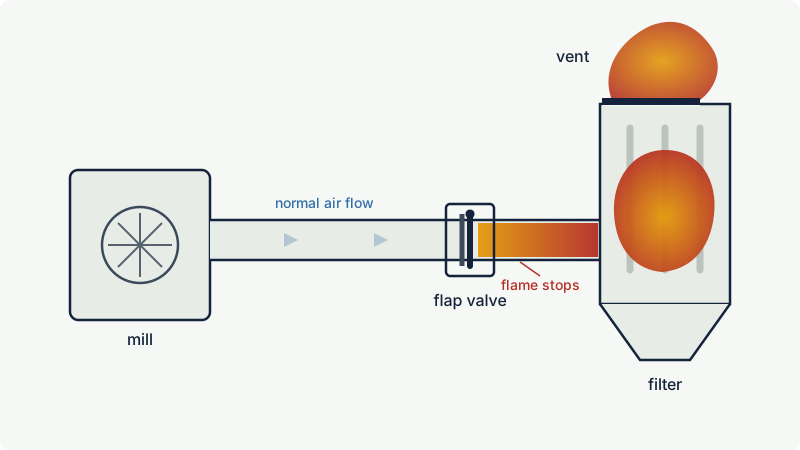
A vented, suppressed or contained vessel is still connected to others by ducts, chutes, pneumatic lines and conveyors. An explosion in one vessel pushes flame and pressure into these connections. The flame accelerates along a duct, and when it reaches the next vessel it arrives as a turbulent jet into a cloud that has already been pre-compressed by the pressure wave. The result, often called pressure piling, can be far more violent than the original explosion and can exceed what the second vessel's own protection was designed for. EN 14491 vent sizing assumes a single, isolated enclosure for this reason.
Passive and active isolation
| Device | Type | How it works | Points to check |
|---|---|---|---|
| Explosion isolation flap valve | Passive | The pressure wave closes a flap against the normal flow direction and a latch holds it shut | Flow direction, installation distance range from the vessel, dust build-up on the flap (EN 16447) |
| Rotary valve as isolation device | Passive | Rigid metal vanes with small clearances to the housing stop flame transmission and withstand the pressure; gap width and gap length both matter | Must be certified for this duty; gap wear; must stop on detection |
| Material choke | Passive | A permanent plug of product, for example a hopper kept above a minimum level, or a screw conveyor with one flight removed and a baffle plate | Level control must be reliable; the choke disappears when the hopper or screw runs empty |
| Fast-acting valve | Active | A detector fires a slide gate or pinch valve that closes in milliseconds | Detector position, closing time versus flame arrival, valve testing |
| Chemical isolation (suppression barrier) | Active | A detector fires an HRD suppressor that fills the duct with suppressant | Detector and suppressor distances, discharge direction, servicing |
| Explosion diverter | Passive | A vented change of direction where the explosion escapes instead of continuing into the downstream duct | Discharge must go to a safe place; use only within its certified scope |
Isolation devices work only within a certified range of distances from the vessel, duct diameters, flow velocities, dust properties and orientations; the installation instructions are part of the protection.
Isolation also includes the controls. HSE guidance stresses that conveying equipment should stop immediately in the event of a fire or explosion, for example via trip switches on vent panels, because a running conveyor or rotary valve keeps moving burning material through the plant.
What happens without isolation
Investigation reports show the pattern. At an ink plant in East Rutherford, New Jersey, in 2012, an explosion in a rooftop dust collector was contained by its suppression equipment, but according to the US Chemical Safety Board (CSB) the pressure reversed the air flow back through the ducts into the pre-mix room, where a flash fire engulfed seven workers. At an aluminium wheel plant in Huntington, Indiana, in 2003, a pressure wave from an explosion in an outdoor dust collector travelled back through the ductwork, and the fireball that followed ignited dust accumulated inside the building; one worker died. More cases are described in Dust collectors, silos and bucket elevators.
Choosing a protection concept
The choice depends on safety, cost, reliability, product contamination and continuity of operation. These questions narrow it down:
| Question | If yes, consider |
|---|---|
| Is the vessel outdoors or next to an outside wall with a safe discharge zone? | Open venting, possibly with a short duct |
| Is the vessel indoors without a safe discharge path? | Flameless venting, suppression or containment |
| Is the product toxic or must it not be released? | Suppression or containment |
| Is the vessel small, round and strong, such as a mill? | Containment designed for Pmax, with isolation |
| Is the dust a metal or St 3 dust? | Check that every device is certified for it; containment or specialist design |
| Is the vessel connected to others? | Isolation on every connection, in both directions where an explosion can start on either side |
| Is product contamination by suppressant unacceptable? | Venting or containment, or a food-compatible suppressant |
A common package for a bag filter outdoors is: vent panels on the dirty side, a passive flap valve or active barrier in the inlet duct, a certified rotary valve at the hopper outlet and, if cleaned air returns into the building, protection of the clean-air duct. Indoors the vent panels are typically replaced by flameless vents or suppression. Building protection, with light roof or wall panels that relieve a room explosion, is a separate design task covered by the same venting standards.
Certification, documentation and inspection
In the EU, a device that is placed on the market separately to halt an incipient explosion or limit its range is a protective system under Directive 2014/34/EU. Article 13 of the directive requires EU-type examination combined with production quality assurance or product verification, or unit verification, for protective systems. Vent panels, flameless vents, suppression systems and isolation devices therefore come with an EU-type examination certificate and instructions that define their limits of use. Equipment protected by such systems is documented in the explosion protection document of the site; see The Explosion Protection Document (EPD). In the USA, NFPA 68 and NFPA 69 set the design and maintenance requirements, and NFPA 660 (2025), which consolidated the former industry and commodity standards for combustible dusts, sets the facility requirements, including the dust hazard analysis that decides where protection is needed.
An inspection checklist for protective systems:
- Vents: panel not painted over, corroded, deformed, blocked by product build-up, snow or ice, or obstructed by new pipework; restraints present; discharge zone still clear and signed; burst indicator working.
- Flameless vents: element clean and undamaged, clearances maintained, no dust deposits nearby.
- Suppression and active isolation: service intervals kept, suppressor pressure and charge verified, detectors clean and tested, control unit faults cleared, interlocks to shut down fans and conveyors working.
- Passive isolation: flap valves free to move and not blocked by deposits, rotary valve clearances within limits, choke levels maintained.
- Changes: any change of product, vessel, duct routing or operating pressure is reviewed against the certificates and the original design.
Common mistakes and misconceptions
- "The filter is vented, so the plant is protected." A vent protects one vessel. Without isolation, the explosion can travel back through the inlet duct into the building, as the incidents above show.
- Using the wrong dust data. Kst and Pmax of the bulk product understate the hazard of the fines that collect in filters and cyclones. Test the dust that is actually present, and recheck after product changes.
- Venting into the building. An indoor vent turns an equipment explosion into a room fire and can raise settled dust into a secondary explosion. Duct the vent outdoors or use a flameless device or suppression.
- Ignoring the rest of the vessel. Pred must be below the strength of the weakest part, including doors, inspection hatches, flexible connections and the hopper of a filter.
- Swapping vent panels without recalculation. A heavier panel, a different opening pressure or a new duct changes the effective vent area. Replacement parts must match the certified design.
- Installing isolation devices outside their certified limits. Distance from the vessel, orientation and flow direction determine whether a flap valve or barrier works.
Frequently asked questions
What is the difference between Pstat and Pred?
Pstat is the overpressure at which an explosion vent opens. Pred is the highest overpressure reached inside the vented (or suppressed) vessel during the explosion. Pred is always higher than Pstat, and the vessel must be designed to withstand Pred.
Do I need explosion isolation if my dust collector is vented?
Yes, wherever the collector is connected to other equipment or to a building through ducts, chutes or conveyors through which an explosion can travel. Venting limits the pressure inside the collector but does nothing to stop flame and pressure passing through the inlet duct or the dust discharge. Isolation devices such as flap valves, chemical barriers or certified rotary valves close these paths.
Can explosion vents discharge inside a building?
Open vents should not discharge into buildings or occupied areas, because they release a fireball and a pressure wave that can injure people and raise settled dust. Indoor equipment is protected with a vent duct leading outdoors, a flameless venting device certified for the dust, explosion suppression or containment.
What is flameless venting?
Flameless venting is explosion venting through a device that quenches the flame and retains most of the burning dust, typically with a metal mesh element behind a bursting panel. It allows venting indoors, but needs a larger vent area than an open vent, has a certified scope of dusts and volumes, and still releases hot gas and pressure close to the device.
Is explosion suppression better than venting?
Neither is better in general. Suppression keeps the explosion inside the vessel at a low pressure and is preferred indoors and for toxic products, but it is an active system that needs regular servicing. Venting is passive and simpler, but needs a safe place for the discharge. Both need isolation of connected equipment.
How strong must a vessel be for explosion protection?
Without venting or suppression, it must withstand the maximum explosion pressure Pmax of the dust, often 8 to 10 bar. With venting or suppression, it must withstand the reduced pressure Pred chosen in the design, often a fraction of a bar. EN 14460 allows explosion-pressure-shock-resistant designs that may deform permanently but must not rupture.
Related on excodex
- Dust collectors, silos and bucket elevators: where dust explosions start
- Dust explosion parameters explained: Kst, Pmax, St classes, MIE and minimum ignition temperatures
- Explosion protection strategy: avoid the atmosphere, avoid ignition, limit the effects
- Deflagration, detonation and overpressure: what happens in a gas or dust explosion
- Dust layers and housekeeping: how thick is too thick?
- Standards spaces: EN 1127-1, ATEX 2014/34/EU, ATEX 1999/92/EC; questions in the forum
Standards and further reading
- EN 14491:2012, dust explosion venting protective systems (vent area calculation for vessels and buildings, vent ducts, flame and pressure effects outside the vent).
- NFPA 68 (2023 edition), explosion protection by deflagration venting; NFPA 69 (2024 edition), explosion prevention systems, including suppression, isolation and containment.
- EN 14797:2006, explosion venting devices (requirements and testing of vent panels and doors, venting efficiency).
- EN 16009:2011, flameless explosion venting devices.
- EN 14373:2021+A1:2025, explosion suppression systems (design, application and effectiveness testing).
- EN 15089:2009, explosion isolation systems; EN 16447:2014, explosion isolation flap valves.
- EN 14460:2018, explosion resistant equipment (explosion-pressure-resistant and explosion-pressure-shock-resistant designs).
- EN 1127-1, explosive atmospheres, explosion prevention and protection, basic concepts and methodology.
- NFPA 660 (2025), standard for combustible dusts and particulate solids, which consolidated NFPA 61, 484, 652, 654, 655 and 664: nfpa.org
- Directive 2014/34/EU, definition of protective systems (Article 2) and conformity assessment (Article 13): legislation.gov.uk, Article 13
- HSE, HSG103 Safe handling of combustible dusts: precautions against explosions (venting, suppression, containment, isolation, siting): hse.gov.uk (free PDF)
- US Chemical Safety Board, investigation of the 2012 flash fire in East Rutherford, New Jersey (dust collection system design): csb.gov
- US Chemical Safety Board, investigation of the 2003 aluminium dust explosion in Huntington, Indiana: csb.gov
This article is general technical information prepared by the excodex editorial team. It does not replace the applicable standards, the equipment certificates and instructions, national regulations or the assessment of a competent person.