Can Ex i circuits be terminated inside an Ex e or Ex d enclosure?
Abstract
Yes, if the enclosure's certificate covers it and the intrinsically safe terminals are kept at least 50 mm from other terminals, or behind a suitable partition, and clearly identified. The box then cannot be opened live unless its non-IS parts are isolated or covered.
Yes, it is common practice, under conditions. The enclosure's certificate and documentation must cover the arrangement, the intrinsically safe (IS) terminals must be separated from all other terminals by at least 50 mm or by a suitable partition, and they must be identified so nobody confuses the circuits. The price is that the enclosure can no longer be opened freely for live work on the IS circuits, because it also contains circuits protected by Ex e or Ex d.
Short answer
- Mixed boxes are allowed: nothing in the standards forbids IS and non-IS circuits in one Ex e or Ex d enclosure, provided intrinsic safety is protected from the other circuits.
- Separation of terminals: at least 50 mm between bare conducting parts of IS and non-IS terminals, or an insulating or earthed metal partition that reaches to within 1.5 mm of the enclosure walls or gives 50 mm measured around it.
- Between separate IS circuits at least 6 mm, and at least 3 mm from IS terminals to earthed metal, under IEC 60079-14.
- IS terminals are marked where confusion is possible; if colour is used it is light blue.
- The enclosure keeps its own type of protection: Ex e or Ex d rules for the box, the entries and the contents still apply, and the certificate decides what may be fitted.
Why the separation matters
Intrinsic safety depends on the energy in the IS circuit staying within the limits of its associated apparatus. If a loose wire from a 230 V or 24 V power circuit touches an IS terminal, the IS circuit suddenly carries energy that no barrier was designed for, possibly out into Zone 0 or Zone 1 equipment. The installation rules for IS circuits are therefore all about keeping other energy out.
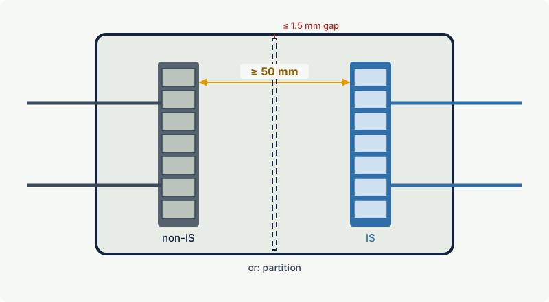
IEC 60079-11 (for apparatus design) and IEC 60079-14 (for installation) both set the 50 mm or partition rule. The layout must also make contact unlikely if a wire comes loose, for example by securing conductors near their terminals and routing IS and non-IS wiring on opposite sides. Inside the box, IS conductors are not bundled with non-IS conductors unless an insulating layer or an earthed metal partition separates them, or one of the two groups is screened or metal-sheathed. IEC 60079-11 adds that metal partitions are earthed and at least 0.45 mm thick, insulating partitions at least 0.9 mm thick, unless they meet an alternative test. An interpretation of IEC 60079-11 confirms the same 50 mm separation for level ic circuits.
What the enclosure and its certificate decide
Ex e enclosures. An Ex e junction box is certified with a defined arrangement of terminals, conductors and power. Many certificates include IS terminals with a defined separation, often on a separate rail behind a partition. Fit only what the certificate and the manufacturer's instructions allow; adding a rail of IS terminals to a box certified without them is a modification. IEC 60079-7 also addresses live maintenance: where the instructions permit live work on the IS circuits inside an Ex e enclosure, either the cover carries a warning not to open it while the non-IS circuits are energised, or the bare live non-IS parts sit behind an internal cover of at least IP30 with its own warnings.
Ex d enclosures. The flameproof enclosure contains whatever its certificate allows, and IS terminals inside it follow the same separation rules. The IS cables enter through entry devices suitable for the Ex d enclosure, because the enclosure's protection depends on them. A flameproof enclosure cannot be opened in the hazardous area while non-IS circuits inside are energised, unless the area is confirmed gas-free under the site's procedures, so live work on the IS circuits in that box is lost.
Typical design. Associated apparatus is often installed in Zone 1 inside a flameproof enclosure, marked for example Ex db eb [ia Ga] IIC T4 Gb: the barrier or isolator sits in the Ex d part, and the IS outputs leave through a separate Ex e terminal compartment where they are kept apart from the power terminals.
Practical case: a mixed field junction box
A skid needs one junction box in Zone 1 for six 24 V solenoid valves (Ex mb) and eight IS transmitters (Ex ia). Options:
| Option | Advantage | Drawback |
|---|---|---|
| Two boxes: Ex e for solenoids, IS-only box for transmitters | IS box can be opened live for loop work; simplest segregation | Two boxes, two cable routes |
| One certified Ex e box with partitioned IS rail | One box, one location | Opening it needs the solenoid circuits isolated, or a certified internal IP30 cover |
Either is acceptable. The single box must have a certificate covering the IS terminals and partition, light blue identification of the IS rail, IS and non-IS cables entering on their own sides, and the separation kept after every modification.
Common mistakes
- Putting IS terminals on the same rail as power terminals with only a spacer terminal between them.
- Long loose tails that could swing across the 50 mm gap if a terminal screw loosens.
- Running IS and non-IS cores in one multicore cable into the box; IEC 60079-14 does not allow this except under restricted conditions.
- Opening a mixed Ex e box live "to work on the IS side" without the internal cover or isolation the certificate requires.
Related on excodex
- Combined protection concepts: Ex db eb, Ex d e terminal boxes and multiple markings
- Intrinsic safety (Ex i): ia, ib and ic and the energy limitation principle
- Ex installation basics under IEC 60079-14
- Can intrinsically safe and non-IS cables run in the same cable tray?
- Can you add extra terminals or conductors to an Ex e junction box?
Standards and further reading
- IEC 60079-14, design, selection and installation (termination and identification of IS circuits).
- IEC 60079-11, equipment protection by intrinsic safety "i" (terminal separation, partitions).
- IEC 60079-7, equipment protection by increased safety "e" (IS circuits and live maintenance in Ex e enclosures).
- IEC 60079-11:2011 text with interpretation sheet 3 on level ic: law.resource.org
- IEC 60079-7:2015 text: law.resource.org
- IEC 60079-14:2007 as AS/NZS 60079.14:2009: archive.org
- Health and Safety Authority (Ireland), instrumentation guidance on intrinsic safety: hsa.ie
This article is general technical information prepared by the excodex editorial team. It does not replace the applicable standards, the equipment certificates and instructions, national regulations or the assessment of a competent person.