Combined protection concepts: Ex db eb, Ex d e terminal boxes and multiple markings
Abstract
Ex db eb means one product protected by two concepts, typically a flameproof motor or switch part with an increased safety terminal box. How combined equipment is certified and marked, and how to read strings with brackets, slashes and two lines.
A combined marking such as Ex db eb means that one product uses two (or more) types of protection, each for a different part. The classic case is a flameproof motor or switching part (db) with an increased safety terminal box (eb), often called an "Ex d e" design. The product has one certificate covering all parts, and one marking string with a single gas group, temperature class and EPL that apply to the whole.
This article explains why concepts are combined, how combined equipment is certified, which motors, luminaires and control devices typically carry combined markings, and how to read strings that contain several concepts, brackets, slashes or a second line for dust.
Key points
- A combined marking lists the symbol of every type of protection used in the product, for example
Ex db eb IIB T4 Gbfor a flameproof motor with an increased safety terminal box. - By convention the symbols appear in alphabetical order, so the order does not tell you which concept protects the largest part.
- The string carries one gas group, one temperature class and one EPL for the whole product: the most restrictive group of any part, the hottest surface of any part, and the protection level the complete product achieves.
- Combined equipment is certified as one product: the certificate lists every standard applied (for example IEC 60079-0, -1 and -7) and covers the interfaces between the parts, such as bushings through a flameproof wall.
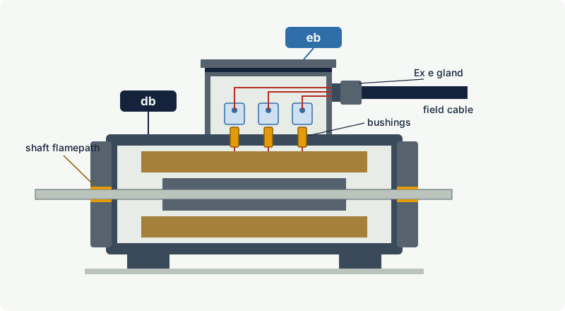
- The main practical reason for combining is indirect entry: field cables terminate in the Ex e compartment with simple glands, while the sparking or hot parts stay inside the flameproof compartment.
- Brackets mark associated apparatus inside the product (for example
[ia Ga]), a slash marks equipment mounted across a boundary between areas needing different EPLs (Ga/Gb), and gas and dust markings are written as separate strings.
Why combine protection concepts?
No single type of protection is ideal for every part of a product. Flameproof enclosures can contain anything, including sparking contacts and hot windings, but they are heavy and their cable entries are demanding. Increased safety is light, cheap and easy to wire, but nothing inside it may spark. Encapsulation suits small electronics, intrinsic safety suits signal circuits. Designers therefore protect each part with the concept that fits it best and join the parts in one certified product. The comparison of the two most common concepts is in Ex d or Ex e.
The most important benefit is the terminal compartment. In a flameproof motor with an Ex e terminal box, the winding leads pass from the flameproof frame into the terminal box through certified bushings that form part of the flameproof boundary. The installer only ever opens the Ex e box, connects the cables to Ex e terminals, and uses Ex e glands. No barrier glands, no flameproof threads to protect, and no risk of damaging a flamepath during wiring.
How combined equipment is certified
Combined equipment is assessed and certified as a single product, not as a collection of separately approved parts.
- Each part is assessed to its own standard. The flameproof part to IEC 60079-1, the increased safety part to IEC 60079-7, an encapsulated driver to IEC 60079-18, and so on, all together with the general requirements of IEC 60079-0. The certificate lists every standard and edition applied.
- The interfaces are assessed too. Bushings and terminal studs that pass through a flameproof wall are part of the flameproof boundary and are tested with it. Heat from the flameproof part that reaches the Ex e compartment counts towards the Ex e part's temperature limits, and the cable entry temperature is measured in the terminal box.
- Ex Components can be used as building blocks. Flameproof switching elements, Ex e terminals and empty Ex e enclosures are often certified as Ex Components (certificate number ending in
U), with a schedule of limitations. IEC 60079-7 givesEx eb IIC Gbas a typical marking for an Ex Component enclosure. A component certificate alone does not allow use in a hazardous area: the finished product needs its own equipment certificate. From IEC 60079-0 edition 8 (2026) the temperature range of an Ex Component must be stated in its schedule of limitations, which makes the combination easier to assess. See the X and U suffixes. - One certificate, one set of conditions. Under IECEx this is one Certificate of Conformity; under ATEX, for a category 2 electrical product, one EU-type examination certificate. Any specific conditions of use (
X) apply to the product as a whole.
Note: An enclosure builder who fits certified flameproof contact blocks, terminals and glands into a certified Ex e enclosure has made a new product. It needs to fall within the configurations allowed by an existing equipment certificate (many control station certificates define permitted component lists, quantities and power limits) or be certified in its own right.
The European Commission's ATEX guidelines treat a product formed by connecting separately certified items into a functional unit as an assembly. The person who places it on the market becomes its manufacturer and must assess the ignition hazards that arise from the combination. That is a related but different situation from a combined product designed and certified as one piece of equipment.
How combined equipment is marked
One string for the whole product
The marking of combined equipment is a single string:
Ex + the symbols of all types of protection used + gas group + temperature class + EPL
for example Ex db eb IIB T4 Gb. The supporting elements apply to the whole product:
- Gas group: the most restrictive of the parts. A flameproof motor tested for IIB with an Ex e terminal box that alone would be IIC is marked IIB.
- Temperature class: the highest surface temperature of any part the atmosphere can reach.
- EPL: the protection level the complete product achieves. A product with a
dbpart and anecpart exposed to the same atmosphere cannot claim Gb.
By convention the symbols are listed in alphabetical order, precisely so that no meaning is read into the sequence. Examples published by IEC follow this convention, such as Ex db h IIA T4 Gb for equipment with an electrical flameproof part and a non-electrical part. Alphabetical order means you cannot tell from the string whether the flameproof part is the motor body or a small switch. Read the certificate's description to find out which part uses which concept.
Old and new forms
Combined equipment has been around for decades, so you will meet several forms on existing plant:
| Form on the label | Era and meaning |
|---|---|
EEx de IIC T4 | European EN 50014 series (withdrawn in 2008); "EEx" with the type letters run together |
Ex de IIB T4 or Ex d e IIB T4 | IEC and EN editions before levels were added to the type symbols |
Ex d e IIB T4 Gb | After EPLs were introduced (EN 60079-0:2009 in Europe) |
Ex db eb IIB T4 Gb | Current form; level letters (db, eb) from IEC 60079-1:2014 and IEC 60079-7:2015 |
All four may describe essentially the same flameproof motor with an increased safety terminal box. The certificate, not the shape of the string, decides what the equipment is certified to.
Brackets: associated apparatus inside the product
Square brackets mark a circuit that the product supplies to somewhere else, which is protected at a different level. Ex db [ia Ga] IIC T4 Gb describes a flameproof housing (Zone 1, EPL Gb) that contains associated apparatus providing an intrinsically safe ia circuit suitable for a Ga location, for example a sensor inside a tank. In ATEX terms this is a category 2 product containing a safety device for category 1 equipment, marked II 2(1) G. See intrinsic safety.
Slash: equipment across a boundary
Some equipment is mounted in a wall between two areas that need different EPLs, such as a level transmitter in the roof of a tank with Zone 0 inside and Zone 1 outside. IEC 60079-26 sets the construction, testing and marking requirements for this "equipment with separation elements". The marking shows both protection levels separated by a slash, typically in a form such as Ex ia/db IIC T4 Ga/Gb, and the ATEX category is written II 1/2 G (the European Commission's ATEX guidelines use this example for a level gauge in a tank wall). The part on the left of the slash faces the more hazardous side. IEC 60079-26 also covers a different idea: combining two independent types of protection, each giving EPL Gb, to reach EPL Ga.
Gas and dust: two lines, not one
IEC 60079-0 states that the marking for explosive gas atmospheres and the marking for explosive dust atmospheres should not be combined into one string. A product suitable for both carries two lines, for example:
II 2 G Ex db eb IIC T4 GbII 2 D Ex tb IIIC T135 °C Db
Two lines mean the product may be used in a gas area or in a dust area. They do not by themselves mean it has been assessed for a hybrid mixture of gas and dust present at the same time. See hybrid mixtures.
Electrical plus non-electrical
A product with electrical and non-electrical ignition sources, such as a motor and gearbox certified as one unit, carries one combined string with h in its alphabetical place. An interpretation sheet to IEC 60079-0 (2018) gives Ex db h IIA T4 Gb and Ex h tb IIIC T135 °C Db as examples. Where the electrical and non-electrical parts have separate certificates, separate strings with their own certificate numbers are appropriate. See non-electrical equipment (Ex h).
Typical combined equipment
| Equipment | Typical combined marking | What each concept protects |
|---|---|---|
| Cage induction motor | Ex db eb | Flameproof frame, windings and rotor; increased safety terminal box |
| Local control station, push buttons | Ex db eb | Flameproof contact blocks inside an increased safety enclosure |
| Control panel or distribution board | Ex db eb | Flameproof switchgear compartment; increased safety terminal compartment (indirect entry) |
| LED or fluorescent luminaire | Ex db eb, Ex eb mb | Flameproof or encapsulated driver and lamp parts; increased safety housing and terminals |
| Plug and socket | Ex db eb | Flameproof switching chamber; increased safety connection parts |
| Gas transmitter, flameproof housing | Ex db ia or Ex db [ia Ga] | Flameproof electronics housing; intrinsically safe sensor or output circuit |
| Level transmitter in a tank roof | Ex ia/db with Ga/Gb | Intrinsically safe probe in Zone 0; flameproof head in Zone 1 |
These are typical patterns, not a catalogue; always check the actual label and certificate.
Reading a combined marking step by step
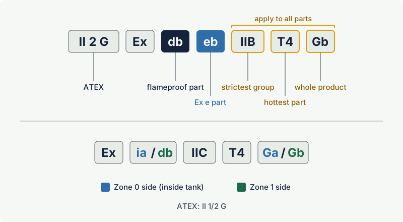
Use this sequence on any combined string:
- Split the string. Separate the ATEX part (
II 2 G), the type-of-protection symbols (db eb), and the gas group, temperature class and EPL. - Assign each symbol to a part. The certificate or instructions say which part is flameproof, which is increased safety, which is encapsulated or intrinsically safe.
- Apply group, class and EPL to the whole. Check them against the area classification exactly as for single-concept equipment. If any of them does not fit, the product does not fit.
- Look for brackets and slashes. Brackets mean a circuit leaving the product for another location; check the connected device and cable parameters. A slash means a boundary product; check which side faces which zone.
- Look for a second line and the X. A second string covers dust. An
Xafter the certificate number means specific conditions of use that may restrict entries, ambient temperature or opening.
Worked example
A pump motor nameplate reads II 2 G Ex db eb IIB T4 Gb, certificate ending in X, -20 °C ≤ Ta ≤ +50 °C. The area is Zone 1 with ethanol vapour (IIB, autoignition temperature 400 °C, T2), and the hottest site ambient is +45 °C.
II 2 GandGb: suitable for Zone 1. Pass.IIB: ethanol is IIB in the excodex library (some North American lists place it in group IIA or D). Pass either way.T4(135 °C) is well below 400 °C. Pass.- Ambient +45 °C lies inside the marked range. Pass. (The normal ambient range is -20 °C to +40 °C; earlier editions of IEC 60079-0 required the range to be marked only when it differed, while edition 8 (2026) requires it on every Ex marking.)
db eb: the field cables go into the increased safety terminal box. The installer uses Ex e glands that keep the box's IP rating and connects to the certified terminals. The flameproof frame is not opened.X: the certificate's specific conditions must be read, for example on bolt replacement or permitted cable entries, before the installation is signed off.
Had the plant handled hydrogen, the IIB would have failed even though the Ex e terminal box on its own might be IIC: the gas group applies to the whole product.
Installation and maintenance of combined equipment
Treat each part according to its own concept:
- Wire only in the compartment intended for it. On an
Ex db ebproduct, field wiring goes into the Ex e compartment. Do not move cable entries into the flameproof part unless the certificate provides for it. - Leave the bushings alone. The bushings or terminal studs between compartments are part of the flameproof boundary. Do not remove, rotate or replace them with non-original parts.
- Apply the right inspection checks to each part. Flamepaths, bolts and stopping plugs on the flameproof part; terminal tightness, conductor count, gaskets and IP rating on the Ex e part; cable parameters on any intrinsically safe circuit. IEC 60079-17 structures its inspection schedules by type of protection, so a combined product appears in more than one column.
- Respect the terminal loading. The Ex e compartment of a combined product has the same limits on terminals, conductors and currents as a stand-alone Ex e box.
- Repair to the right standard. Work on the flameproof part, such as remachining a shaft flamepath, falls under the flameproof repair rules of IEC 60079-19; rewinding affects the temperature data of the whole motor. See repair, overhaul and modification.
Common mistakes
- Reading the first symbol as the "main" concept. Symbols are listed alphabetically;
dbcomes beforeebwhatever their relative size. - Taking the gas group of one part. An Ex e terminal box rated IIC on a IIB flameproof motor does not make the motor IIC. The whole product is marked with the most restrictive group.
- Adding a cable entry to the flameproof part. It bypasses the indirect-entry design, needs flameproof glands and must be covered by the certificate. Keep field wiring in the Ex e compartment.
- Building a control station from certified parts and assuming it is certified. Component (
U) certificates do not certify the finished product. Use a certified configuration or have the assembly certified. - Merging gas and dust lines in documentation.
II 2 GDwith one string hides which group, temperature and EPL apply to which atmosphere. Keep the two strings as marked. - Ignoring a slash. On boundary equipment, the Ga side must face the Zone 0 side; mounting it the wrong way round defeats the separation element.
Frequently asked questions
What does Ex db eb mean?
It means the product is protected by two types of protection: a flameproof enclosure at level db and increased safety at level eb. Typically a flameproof motor, switch or driver compartment is combined with an increased safety terminal box or housing. Both parts are EPL Gb, so the product is suitable for Zone 1 and Zone 2.
Is Ex de the same as Ex db eb?
Generally yes: Ex de (or EEx de) is the older form for the same idea, a flameproof part combined with an increased safety part. The level letters b were added to d and e by IEC 60079-1:2014 and IEC 60079-7:2015. The equipment remains certified to the editions stated on its certificate.
Why do motors have an increased safety terminal box?
Because it simplifies installation and maintenance. The cables are connected in an Ex e box with ordinary Ex e glands, and only factory-sealed bushings pass into the flameproof frame. The installer never opens a flamepath, and barrier glands are not needed.
Which gas group applies when parts have different groups?
The most restrictive one. The marking of a combined product carries a single gas group that every part satisfies, so a IIB flameproof part limits the whole product to IIB, even if other parts would meet IIC.
What does a slash in an Ex marking mean, as in Ga/Gb?
The equipment is designed to be mounted across a boundary between two areas needing different EPLs, typically a tank wall with Zone 0 inside and Zone 1 outside. The symbols before the slash refer to the more hazardous side. The requirements are in IEC 60079-26, and the ATEX equivalent is a category marked 1/2.
Can one product have both a gas and a dust marking?
Yes. It then carries two separate strings, one with a gas group, temperature class and G-level EPL, the other with a dust group, maximum surface temperature in °C and D-level EPL. Each applies to its own type of atmosphere.
Related on excodex
- Ex d or Ex e? Choosing between flameproof and increased safety
- How to read an Ex marking: decoding II 2 G Ex db IIC T4 Gb step by step
- Ex protection concepts at a glance
- The X and U suffixes on Ex certificates
- Equipment Protection Levels (EPL) and how they match zones
- Tools and spaces: Ex marking check, standards spaces IEC 60079-0, IEC 60079-26, IECEx, forum
Standards and further reading
- IEC 60079-0, general requirements, including marking (edition 8, 2026).
- IEC 60079-1 (flameproof "d"), IEC 60079-7 (increased safety "e"), IEC 60079-11 (intrinsic safety "i"), IEC 60079-18 (encapsulation "m").
- IEC 60079-26, equipment with separation elements or combined levels of protection (edition 4, 2021).
- IEC 60079-14 (installation), IEC 60079-17 (inspection and maintenance), IEC 60079-19 (repair).
- IEC webstore, IEC 60079-26:2021 scope summary: webstore.iec.ch
- IEC 60079-0:2011 interpretation sheet 3 (2018), combined marking of electrical and non-electrical equipment: iecex.com
- IECEx ExTAG compilation of comments on the marking of combined electrical and non-electrical equipment (2017): iecex.com
- European Commission, ATEX 2014/34/EU Guidelines, 6th edition (January 2026), sections on assemblies and on marking of equipment with different categories: single-market-economy.ec.europa.eu
This article is general technical information prepared by the excodex editorial team. It does not replace the applicable standards, the equipment certificates and instructions, national regulations or the assessment of a competent person.