Ex d or Ex e? Choosing between flameproof and increased safety for motors and junction boxes
Abstract
Ex d contains an internal explosion; Ex e stops sparks and hot spots from occurring. How the two compare for junction boxes and motors: cable entries, gas group, tE time, weight, cost and maintenance, with a selection guide.
Ex d and Ex e reach the same safety level, EPL Gb for Zone 1, by opposite routes. A flameproof enclosure (Ex d) lets the gas inside ignite, withstands the explosion and stops the flame from escaping. Increased safety (Ex e) makes sure that nothing inside can ignite the gas in the first place: no arcs, no sparks, no hot spots. For enclosures that only hold terminals, and for most cage induction motors, Ex e is usually lighter, cheaper and easier to install; flameproof protection is needed for parts that spark in normal operation, and an Ex d motor is the usual answer when the motor's thermal behaviour does not suit Ex e.
This article compares the two concepts side by side for junction boxes and motors, and explains what the choice means for cable entries, gas group, temperature class, motor protection, weight, cost and maintenance.
Key points
- Ex d (IEC 60079-1) contains an internal explosion and cools the escaping gases in narrow flamepaths; Ex e (IEC 60079-7) prevents ignition sources by design. Levels db and eb both give EPL Gb; dc and ec give EPL Gc.
- Ex e cannot house anything that sparks in normal operation, such as switches, contactors or relays. Those need a flameproof enclosure or flameproof components (which leads to combined
Ex db ebequipment). - In Ex e the temperature limit applies to every part the gas can reach, inside and outside; in Ex d it applies to the outer surface, so the inside may be hotter.
- Cable entry is the biggest practical difference: Ex d needs flameproof glands with the right thread, and IEC 60079-14 decides when a barrier (compound) gland is required. Ex e needs certified glands that keep the enclosure's ingress protection, at least IP54 where bare live parts are present.
- An Ex eb motor for line starting is marked with its starting current ratio IA/IN and its tE time; the overload protection must disconnect a stalled motor before tE elapses. IEC 60079-7 does not allow tE below 5 s with a current-dependent device or IA/IN above 10.
- Ex d design depends strongly on gas group (gaps, joint types and obstruction distances get stricter from IIA to IIC); most Ex e terminal boxes are certified for IIC because the concept hardly depends on the gas.
Two ways to reach EPL Gb
A flameproof enclosure assumes the explosive atmosphere will get inside, because joints are not gas-tight and enclosures breathe as they warm and cool. When something inside ignites it, the walls withstand the pressure and every joint acts as a flamepath that quenches the flame. The full mechanism is explained in flameproof enclosures (Ex d).
Increased safety takes the opposite view. The gas may reach the live parts, so the live parts must never become an ignition source, either in normal operation or in the faults the standard considers for the level. This is achieved by high-quality terminals that cannot loosen, generous creepage and clearance distances, tested insulation, an enclosure with a defined ingress protection, and strict limits on the temperature of every part. See increased safety (Ex e).
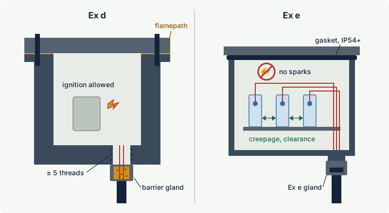
The consequence is easy to remember: Ex d tolerates sparks, Ex e does not. A junction box with only terminals can be either. A control station with push buttons, a contactor or a circuit breaker cannot be plain Ex e; the switching parts must be flameproof, either inside a complete Ex d enclosure or as small flameproof switching elements fitted into an Ex e enclosure.
Side-by-side comparison
| Aspect | Ex d (flameproof, level db) | Ex e (increased safety, level eb) |
|---|---|---|
| Principle | Ignition inside is allowed; enclosure contains it and quenches the flame | No ignition source is allowed to occur |
| Standard | IEC 60079-1 | IEC 60079-7 (edition 5.1, 2015 + amendment 2017) |
| Sparking devices inside | Allowed (switchgear, contactors, slip rings) | Not allowed; use flameproof components (combined marking) |
| Temperature class refers to | Outer surface of the enclosure | All surfaces the gas can reach, inside and outside |
| Gas group sensitivity | High: gaps, joint types and obstruction distances depend on IIA, IIB, IIC | Low for terminal boxes, which are commonly IIC; some motor tests depend on the group |
| Typical enclosure | Cast aluminium alloy, cast iron or thick steel; machined flamepaths | Sheet or cast metal, stainless steel or glass-reinforced plastic with a gasket |
| Ingress protection | Not the basis of protection (often specified for the environment) | Part of the protection: at least IP54 with bare live parts, IP44 with insulated live parts only |
| Cable entry | Flameproof glands, correct thread, at least five threads engaged; barrier gland where IEC 60079-14 requires it; or conduit with sealing fittings | Certified Ex e glands that maintain the IP rating, in threaded or plain (clearance) holes as the gland instructions allow |
| Internal changes | Very limited: free volume and layout are part of the certification | Limited by the certified terminal loading or power dissipation |
| Weight and size | Heavy; IIC versions often heavier and dearer | Light; often larger box for the same number of terminals |
| Typical failure found on inspection | Damaged, corroded or painted flamepaths, missing bolts, wrong glands or plugs | Loose terminals, overfilled terminals, damaged gaskets, IP lost at entries |
Junction boxes and terminal enclosures
For a box that only connects cables, Ex e is the usual choice in IEC-based practice, and a heavy flameproof box is used only when there is a specific reason.
What decides the temperature class of an Ex e box
Current flowing through terminals and conductors produces heat, and in an Ex e box that heat counts towards the temperature class because the gas is in contact with it. The certificate therefore limits the terminal loading: how many terminals of which size, how many conductors per terminal, what cross-sections and what currents. IEC 60079-7 describes two approaches for general purpose junction boxes: a defined table of permitted terminal and conductor combinations, or a maximum internal power dissipation that the user checks by calculation. Adding terminals, increasing currents or using a smaller box than the table allows can push the inside above the temperature class even though nothing sparks.
Why Ex d boxes still exist
A flameproof junction box is chosen when the box also contains switching or protective devices, or components that cannot meet Ex e rules. Internal dissipation then matters only for the outer surface temperature. The price is weight, machined joints that must be protected for life, and more demanding cable entries.
Cable entry consequences
Entries into Ex d
A cable entering a flameproof enclosure becomes part of the flameproof boundary, because the gland and the cable together must stop an internal explosion from passing along the cable. The entry device must be certified for flameproof use with the correct thread form and at least five full threads engaged (see flameproof enclosures). IEC 60079-14 (edition 2024) contains a selection method for entries into Ex d enclosures, a section on which cables are suitable for direct entry, and a normative pressure test procedure for cables. Depending on the cable construction and the application, a gland with an elastomeric seal may be accepted, or a barrier gland, which seals around each core with a setting compound, is required. Barrier glands take longer to install, need the compound to cure, and are difficult to re-make.
Two alternatives avoid this: a conduit system with flameproof sealing fittings, which is common where the installation practice is based on conduit, and indirect entry, where the cables terminate in an Ex e terminal compartment and only factory-made bushings pass into the flameproof part. Indirect entry is the reason so many motors and control panels are marked Ex db eb; see combined protection concepts.
Every unused entry must be closed with a certified flameproof stopping plug of the right thread, and the flange obstruction distances apply after installation: unless the certificate allows less, keep solid objects at least 10 mm from flanged joints for IIA, 30 mm for IIB and 40 mm for IIC.
Entries into Ex e
An Ex e enclosure relies on its ingress protection and on the integrity of its terminals, so the gland must be certified for Ex e use and must keep the enclosure's IP rating. A clearance hole with a sealing washer and locknut is acceptable where the gland's instructions allow it. Many cable glands are certified for both flameproof and increased safety use, which simplifies stock, but the gland must still match the entry type and the cable. Unused entries are closed with certified blanking elements that maintain the IP rating.
See cable glands for hazardous areas for the selection rules in detail.
Motors: Ex d, Ex e or both
Cage induction motors are the other large application. Here the comparison is more about thermal behaviour than about enclosures.
Ex e motors and the tE time
An Ex e motor is a cage motor built so that no part becomes an ignition source, including during starting and if the rotor is locked. Its winding temperature limits are lower than those of an industrial motor: for a class F (155) insulation system, IEC 60079-7 limits an eb winding to 130 °C in rated service (measured by resistance) and to 210 °C at the end of the locked-rotor time. The rotor cage must stay below its limiting temperature even during starting, and that limit is also governed by the temperature class.
The key motor parameter is the time tE: the time a winding carrying the initial starting current IA takes to heat from its temperature in rated service, at maximum ambient temperature, up to the limiting temperature. If the rotor stalls, a current-dependent protective device must switch the motor off before tE has elapsed. IEC 60079-7 therefore requires line-start eb motors protected in this way to be marked with IA/IN and tE, and sets minimum tE values depending on IA/IN, with an absolute floor of 5 s and a maximum starting current ratio of 10.
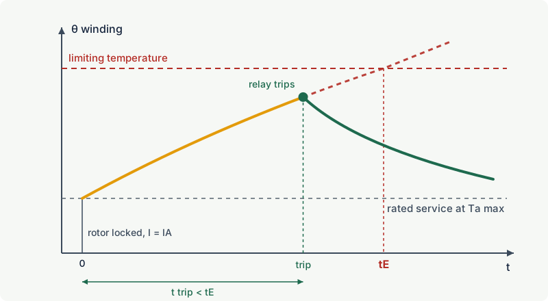
In practice this means the overload relay is not set by habit. Its tripping time at the current ratio IA/IN, read from the relay's time-current characteristic, must be shorter than tE. Alternatively, IEC 60079-7 allows protection by winding temperature sensors with an associated safety device, at least one sensor per phase.
Ex d motors
A flameproof motor encloses the windings, rotor and usually the terminal area in a pressure-resistant frame, with cylindrical flamepaths along the shaft at both end shields. Because ignition inside is tolerated, the winding may get hot internally without creating an ignition risk outside, as long as the outer frame stays within its temperature class. The burden moves to mechanics: a heavier frame, machined shaft flamepaths whose clearances must stay within the certified limits as bearings wear, and an entry system that is either flameproof (an Ex db motor) or an increased safety terminal box (Ex db eb).
Large, high-voltage and converter-fed motors
- Starting sparks and high voltage. IEC 60079-7 requires eb machines (and larger ec machines in certain duty types) to be assessed for possible sparking in the rotor air gap, based on rotor construction, poles, output, cooling ducts and limiting temperature. When the risk score is high, the machine must pass a test in an explosive mixture, or special measures at start (such as pre-start ventilation or internal gas detection) are required as a specific condition of use, or the starting current must be limited. Above 1 kV, the stator insulation of eb machines is tested in an explosive mixture of the relevant gas group, and IEC 60079-14 contains a stator winding discharge risk assessment. The gas group therefore matters for Ex e motors more than for Ex e boxes.
- Converter supply. A motor fed by a variable speed drive runs at varying voltage and frequency and can heat differently. Whichever concept is used, the certificate must cover converter operation; for Ex e machines the documented converter conditions and thermal protection are part of the certification, and IEC 60079-0 edition 8 (2026) added further instruction requirements for converter-driven type e motors.
Gas group sensitivity
A flameproof enclosure is designed around the gas. Permitted gaps shrink from IIA to IIB to IIC, some joint types are restricted for IIC, and the clearance to nearby obstacles grows. A IIB flameproof enclosure is not acceptable for hydrogen or acetylene unless it is additionally marked for hydrogen (IIB + H2, which still excludes acetylene).
Ex e does not rely on quenching a flame, so its construction is largely independent of the gas group, and terminal and junction boxes are commonly certified IIC (the standard's own example of an Ex Component enclosure marking is Ex eb IIC Gb). This makes Ex e attractive on hydrogen, acetylene and ethylene units. The exceptions are the motor tests described above, which are carried out with a test mixture chosen by gas group.
Weight, cost and maintenance
Weight and cost
Flameproof enclosures are cast or machined to withstand explosion pressure and to hold precise flamepath gaps, so they are heavy and need stronger supports. Their cable entries cost more, especially where barrier glands are needed, and installation takes longer. Ex e enclosures are lighter, cheaper and quick to terminate, but may need to be physically larger to stay within the terminal loading for a given number of circuits.
For motors the balance is less clear. An Ex e motor may need a larger frame or a reduced rating to meet the lower winding limits and the tE requirement, and it needs carefully selected protection. A flameproof motor carries the cost of a heavier frame and machined flamepaths. Many users therefore choose by size and duty: Ex e where the motor's starting and thermal data suit, flameproof (often with an Ex e terminal box) where they do not; pressurisation is a further option for very large machines.
Maintenance and inspection
| Topic | Ex d | Ex e |
|---|---|---|
| Opening | Isolate and confirm gas-free conditions; respect any waiting time marked on the enclosure | Isolate and confirm gas-free conditions; live parts are exposed once open |
| Critical surfaces | Flamepaths: no damage, corrosion, paint or hardening sealant; non-setting grease only | Gaskets and sealing faces: intact, correctly seated, no cuts or compression set |
| Fasteners | Every bolt present, correct size, length and strength class | Lid fasteners tight so the IP rating is maintained |
| Terminals | Not part of the protection concept, but must be sound | Correct torque, correct number and size of conductors, no added terminals |
| Entries | Flameproof glands and stopping plugs, correct thread, no plastic caps | IP-rated glands and blanking elements, seals intact |
| Motors | Shaft flamepath gap and bearing condition; frame temperature | Overload relay setting against tE, sensor circuits, cleanliness of windings on high-voltage machines |
Typical findings for both concepts, and how to fix them, are covered in common Ex inspection findings.
Practical case: three items on a Zone 1 compressor skid
A skid in a Zone 1 area handles a process gas containing hydrogen (group IIC) and hexane vapour (autoignition temperature 225 °C, T3). The equipment must therefore be IIC and at least T3. Three items need a decision.
- Instrument and power junction box, terminals only. An
Ex eb IIC T4 Gbbox is light, corrosion resistant in stainless steel, and its cables enter through IP-rated Ex e glands. The designer checks the terminal loading table on the certificate against the number of conductors and currents. A IIC flameproof box would work too, but would be heavier and need flameproof glands. Choice: Ex e. - Local control station with start, stop and an indicator lamp. The contacts spark when operated, so plain Ex e is not possible. The options are an all-flameproof station or an Ex e enclosure with flameproof contact blocks, marked for example
Ex db eb IIC T4 Gb. Both are acceptable; the second keeps Ex e cable entries. Choice: Ex e enclosure with flameproof switching elements. - 55 kW low-voltage compressor motor, direct-on-line. An
Ex eb IIC T3 Gbmotor is possible if its tE at T3 and the chosen overload relay match; the relay curve is checked at the marked IA/IN. If the motor must also run on a converter, the certificate must explicitly cover it. A flameproof motor for IIC is the alternative where the drive or starting duty does not suit Ex e. Choice: Ex eb, with the relay characteristic recorded in the verification dossier.
Common mistakes
- Adding a contactor, relay or switch to an Ex e box. Anything that sparks in normal operation breaks the Ex e concept; only certified flameproof or otherwise protected components listed in the certificate may be fitted.
- Treating Ex e terminal boxes as unlimited. Extra terminals, more conductors per terminal or higher currents than the certificate allows can exceed the temperature class without any visible damage.
- Using an Ex e or industrial gland on a flameproof entry. The gland must be certified for flameproof use and the correct thread; IEC 60079-14 decides whether a barrier gland is needed.
- Setting the overload relay of an Ex e motor by rule of thumb. The tripping time at the marked IA/IN must be shorter than tE; otherwise the winding can reach an ignition-capable temperature during a stall.
- Assuming a IIB flameproof enclosure is fine for hydrogen. Only IIC or
IIB + H2flameproof equipment covers hydrogen, and only IIC covers acetylene. - Believing Ex d is "safer" than Ex e. Both are EPL Gb. A poorly maintained flamepath or a missing bolt can make Ex d less safe than a well-kept Ex e box.
Frequently asked questions
What is the difference between Ex d and Ex e?
Ex d (flameproof) allows an explosion inside the enclosure and contains it, cooling the escaping gases in narrow flamepaths. Ex e (increased safety) prevents arcs, sparks and hot spots from occurring at all. At levels db and eb both give EPL Gb and are suitable for Zone 1 and Zone 2.
Can an Ex e junction box be used for IIC gases such as hydrogen?
Yes, if it is marked IIC. Most Ex e junction boxes carry a IIC marking because the increased safety concept does not depend on quenching a flame. Check the temperature class, the ambient range and the terminal loading on the certificate as well.
Why can't a switch be installed in an Ex e enclosure?
A switch produces a small arc each time it opens or closes, which is an ignition source in normal operation. Ex e only permits parts that do not spark. Switching devices must be flameproof, encapsulated or otherwise protected, and the resulting product carries a combined marking such as Ex db eb.
What is the tE time on an Ex e motor nameplate?
tE is the time a stalled motor's winding takes to heat from its rated-service temperature, at maximum ambient, to the limiting temperature set by the temperature class or the insulation. The motor's overload protection must disconnect it before tE has elapsed. IEC 60079-7 does not accept tE below 5 s for protection by a current-dependent device.
Is Ex e accepted in the North American Division system?
Increased safety is a Zone concept. In the United States it is recognised for Zone 1 and Zone 2 under the Zone system (NEC Article 505), but it is not one of the protection techniques for Class I, Division 1 locations. Check the applicable code and the listing before using Ex e equipment in North America.
Related on excodex
- Flameproof enclosures (Ex d): how flamepaths stop an internal explosion
- Increased safety (Ex e): preventing sparks, arcs and hot spots
- Combined protection concepts: Ex db eb, Ex d e terminal boxes and multiple markings
- Cable glands for hazardous areas: barrier glands, compound glands and selection
- Hot surfaces in hazardous areas: luminaires, motors, heat tracing and process heat
- Tools and spaces: Ex marking check, gas library, standards spaces IEC 60079-1, IEC 60079-7, IEC 60079-14, forum
Standards and further reading
- IEC 60079-1, equipment protection by flameproof enclosures "d".
- IEC 60079-7, equipment protection by increased safety "e" (edition 5.1, the 2015 edition with its 2017 amendment; a sixth edition is in preparation).
- IEC 60079-0, general requirements for Ex equipment (edition 8, 2026).
- IEC 60079-14, design, selection and installation of electrical installations (edition 6, 2024).
- IEC 60079-17, inspection and maintenance of electrical installations.
- IEC webstore, IEC 60079-7:2015+AMD1:2017 consolidated version, scope summary: webstore.iec.ch
- IEC 60079-14:2024 preview with the table of significant changes: cdn.standards.iteh.ai
- Draft sixth edition of IEC 60079-7, project status and change summary: standards.iteh.ai
- M. D. Rad, D. Sălăsan, S. Zsido, new requirements for the evaluation of rotating machines with increased safety, MATEC Web of Conferences 342, 2021 (open access): matec-conferences.org
- Definition of time tE as used in IEC 60079-14: iadclexicon.org
This article is general technical information prepared by the excodex editorial team. It does not replace the applicable standards, the equipment certificates and instructions, national regulations or the assessment of a competent person.