Cable glands for hazardous areas: barrier glands, compound glands and selection
Abstract
How to select Ex cable glands: increased safety, flameproof elastomeric seal and barrier (compound) glands, when IEC 60079-14 requires a barrier gland, IP and ingress, metric and NPT threads, adapters, blanking elements and common mistakes.
A cable gland for a hazardous area must keep the enclosure's type of protection intact where the cable enters, seal against water and dust, and hold the cable (and earth its armour). There are three main families: increased safety (Ex e) glands with an elastomeric seal on the cable sheath, flameproof (Ex d) glands with an elastomeric seal, and barrier glands, in which a compound is cast around the individual cores. A barrier gland is needed on a flameproof enclosure when the cable itself could carry flame or gas through its interior; the 2024 edition of IEC 60079-14 decides this with a flowchart based on gas group, cable length and enclosure volume.
This article explains the gland types, the barrier gland rules in the 2013 and 2024 editions of IEC 60079-14, IP ratings and ingress, thread types and adapters, and the mistakes inspectors find most often.
Key points
- An Ex cable gland must be certified for the type of protection of the enclosure it enters (Ex d, Ex e, Ex t, Ex nR); many glands carry dual certification such as Ex db and Ex eb.
- A gland that seals on the outer sheath does nothing about the gaps between the cores inside the cable; a barrier gland closes those gaps with a compound cast around each core.
- Under IEC 60079-14:2024, a barrier-type entry is required on a flameproof enclosure when less than 3 m of cable is connected in IIC (or IIB + H2), or less than 0.5 m in IIA and IIB; longer cables still need a barrier entry in IIC (or IIB + H2) or on enclosures above 2000 cm³, unless there is reliable evidence that the cable passes the standard's cable test.
- The gland must fit the cable's diameter range; building a cable up with tape or heat-shrink to fit a larger gland is not permitted.
- Unused entries must be closed with blanking elements certified for the type of protection, removable only with a tool and giving at least IP54 (or more where required); plastic transit caps are not blanking elements.
- Metric and NPT threads must never be mixed: an M20 gland can start in a 1/2 in NPT hole and feel tight while engaging only a few threads, because the pitches differ by about 0.3 mm per thread.
What a hazardous area gland has to do
| Function | Why it matters | Typical feature |
|---|---|---|
| Keep the type of protection | The entry is part of the flameproof joint, the increased safety enclosure or the dust-tight enclosure | Certification for Ex d, Ex e, Ex t, Ex nR, or a combination |
| Seal against ingress | Water and dust inside an enclosure cause tracking, corrosion and hot spots | Outer seal on the sheath, entry seal at the thread, IP66 or IP68 rating |
| Retain the cable | Pull or twist on the cable must not reach the terminals | Clamping seal or armour clamp, external cable support |
| Terminate armour or braid | The armour must be bonded so it cannot spark or carry fault current through a poor contact | Armour cone and clamping ring, earth tag where the enclosure is non-metallic |
| Survive the environment | Corrosion, UV and temperature extremes destroy seals and threads | Material (brass, nickel-plated brass, stainless steel, plastic), seal compound, temperature rating, shroud |
Gland types
Increased safety (Ex e) and dust (Ex t) glands
These glands seal on the cable's outer sheath with an elastomeric ring and give a high IP rating. They are used on increased safety terminal boxes and on dust-protected (Ex t) enclosures, where the job of the entry is to keep water and dust out and to retain the cable. Plastic versions are common on non-metallic enclosures; with armoured cable they need a way of bonding the armour, such as an earth tag or a metal gland plate.
Flameproof (Ex d) glands with elastomeric seal
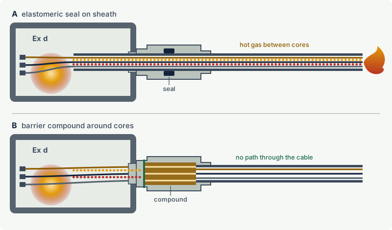
A flameproof gland screws into a threaded entry of an Ex d enclosure and must stop flame passing between the gland and the cable sheath. Its inner seal grips the cable's inner sheath or bedding; an outer seal (on armoured cable glands) keeps water out of the armour. The seal works on the outside of whatever it grips. It cannot close the small channels running along the inside of the cable, between the cores and around the fillers, which are called the interstices.
Barrier glands (compound glands)
In a barrier gland the outer sheath, bedding and fillers are removed over a defined length inside the gland, the cores are separated, and a two-part compound is packed or poured around each individual core. Once cured, the compound forms a solid plug that closes the interstices as well as the space around the cable. Barrier glands are slower to install, need the compound to be mixed, applied and cured exactly as instructed, and cannot be inspected internally afterwards; but they make the entry independent of the cable's internal construction.
Other entry devices
- Mineral insulated cable glands seal the copper sheath of MI cable; MI cable systems are treated as their own case in the flameproof selection rules.
- Restricted breathing (Ex nR) glands keep the restricted breathing properties of the enclosure.
- Conduit sealing fittings (stopping boxes) do the same job as a barrier gland in conduit systems: a compound plug around the conductors.
- Thread adapters and reducers change the thread size or type at an entry, and blanking elements (stopping plugs) close unused entries. Both must be certified for the type of protection.
When is a barrier gland needed?
The question only arises for flameproof enclosures. If the enclosure contains an ignition source and explosive gas is present inside, an internal explosion pushes hot gas and flame into every gap, including the inside of the cable. If the cable interior is open enough, the flame can travel along it and emerge where the cable ends, or the pressure can push gas along the cable into another enclosure or a non-hazardous area. A long, compact cable with solid fillers resists this; a short cable, a cable with loose or absorbent fillers, a large enclosure (more gas, higher pressure) and an easily ignited gas such as hydrogen make it worse.
The rule has changed several times
- Earlier editions (up to the 2007 edition, EN 60079-14:2008 in Europe) used a flowchart based on whether the enclosure contained an internal source of ignition, on whether the gas required IIC equipment, and, for Zone 1 installations, on whether the enclosure volume exceeded 2 litres.
- The 2013 edition simplified this: either a barrier gland certified to IEC 60079-1, or a certified flameproof gland with an elastomeric seal used with a cable meeting the fixed-wiring requirements (circular, compact, extruded bedding, non-hygroscopic fillers) and with at least 3 m of cable connected. Critics noted that the rule did not say clearly where the 3 m was measured or whether coiled cable counted, and a users' association published test results arguing that enclosure volume, which the 2013 rule had dropped, matters more than cable length.
- The 2024 edition introduced a new flowchart and a normative cable test (Annex C) to support it.
The 2024 flowchart in outline
The outline below is reconstructed from published summaries of the new edition (a magazine article by the chair of IEC technical committee 31 and a certification body white paper), not from the standard's own figure, which is not in the public preview. It is consistent across those sources, but the flowchart, its notes and its exact boundary conditions in IEC 60079-14:2024 govern:
- Gas group IIC or IIB + H2. With less than 3 m of cable connected, a barrier-type entry device is required. With 3 m or more, an elastomeric seal gland may be used only if there is sufficient, reliable evidence that the cable meets the Annex C test; otherwise use a barrier.
- Gas group IIA or IIB. With less than 0.5 m of cable connected, a barrier-type entry device is required. With 0.5 m or more and an enclosure of 2000 cm³ or less, an elastomeric seal gland is permitted.
- IIA or IIB, enclosure above 2000 cm³ (or volume unknown, which should be treated as above): an elastomeric seal gland needs Annex C evidence for the cable; otherwise use a barrier.
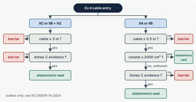
The Annex C test is a pressure test on a sample of the cable that shows how easily gas passes along its interior. It is used only to decide which type of entry device may be used. It does not prove that the cable is gas tight or flameproof, and a catalogue description of the cable is not, on its own, sufficient evidence. The flowchart does not replace the separate requirements for cables entering flameproof enclosures directly: the cable itself must still be of a suitable construction.
Note: A barrier gland is always an acceptable choice on a flameproof enclosure. When the cable length, the enclosure volume or the cable evidence is uncertain, choosing a barrier gland removes the doubt. Record the selection reasoning either way: IEC 60079-14 lists the cable entry selection records as part of the installation documentation.
Worked example
A flameproof control station of about 1.5 litres (1500 cm³) is installed in a IIB area, fed by a compact armoured cable that runs 25 m to a junction box. The gas group is IIB, the connected length is well over 0.5 m, and the volume is below 2000 cm³: an Ex d elastomeric seal gland is acceptable under the 2024 flowchart, provided the cable itself is suitable for direct entry into a flameproof enclosure. The same station in a hydrogen area (IIC) with the same 25 m cable would need Annex C evidence for that cable, or a barrier gland. A 0.3 m flying lead between two flameproof enclosures would need a barrier entry in any gas group.
IP rating and ingress
The IP code (IEC 60529) has two digits. The first is protection against solids: 5 is dust-protected, 6 is dust-tight. The second is protection against water: 4 is splashing, 5 water jets, 6 powerful water jets, 7 temporary immersion and 8 continuous immersion under conditions stated by the manufacturer. IP68 does not automatically include IP66, because jets and immersion are different tests; glands for deluge or washdown areas are often marked with both, for example IP66/IP68.
The gland must keep the IP rating of the enclosure. For increased safety terminal boxes that is normally at least IP54; dust-protected (Ex t) enclosures generally need dust-tight entries. IEC 60079-14 requires blanking elements for unused openings to give at least IP54, or more where the location requires it.
Three places can leak:
- Between the seal and the cable sheath: use the correct seal size for the measured cable diameter and tighten to the instructions.
- At the entry thread: an entry seal (sealing washer or O-ring) or a non-setting thread sealant, as allowed by the gland and enclosure instructions. On a flameproof entry anything fitted under the gland must not reduce the required thread engagement.
- Through the cable itself: water can travel along the inside of a damaged cable. Route cables so that water runs away from the entry (enter from below where possible, form drip loops) and repair damaged sheaths instead of relying on the gland.
Threads, adapters and blanking elements
Thread types
Ex enclosures use mainly two thread systems:
| Size | Thread | Pitch | Major diameter | Form |
|---|---|---|---|---|
| M20 x 1.5 | ISO metric | 1.5 mm | 20.0 mm | Parallel |
| 1/2 in NPT | ASME B1.20.1 | 14 threads per inch (1.814 mm) | about 21.3 mm | Tapered 1 in 16 |
| M25 x 1.5 | ISO metric | 1.5 mm | 25.0 mm | Parallel |
| 3/4 in NPT | ASME B1.20.1 | 14 threads per inch (1.814 mm) | about 26.7 mm | Tapered 1 in 16 |
Older equipment may also have PG threads, a German conduit thread system largely replaced by metric threads. The thread type and size of each entry are stated on the enclosure or in its documentation; check them before ordering glands.
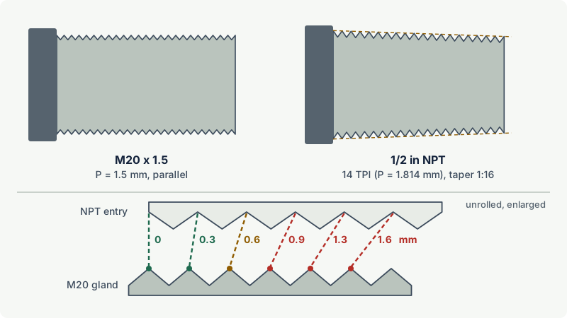
For flameproof entries, the threads are part of the flamepath. Parallel threads need at least five full threads engaged; tapered threads have their own engagement rules in IEC 60079-1. Hence: never force a gland, never use a gland with damaged threads, and never use thread tape on an Ex d entry unless the instructions explicitly allow a specific product.
Adapters and reducers
Adapters convert a thread type or size, for example from 3/4 in NPT to M20. They must be certified for the protection type, they add a joint, and on a flameproof enclosure IEC 60079-14 forbids using an adapter together with a blanking element. Manufacturers' instructions typically allow only one adapter or reducer per entry; stacking them is a common inspection finding.
Blanking elements
Unused entries must be closed with blanking elements suitable for the type of protection, removable only with a tool, and giving at least IP54 or the IP required by the location. On a flameproof enclosure that means a certified flameproof stopping plug with the correct thread and engagement. Plastic dust caps fitted for transport are not blanking elements and must be removed at installation.
Installing a gland correctly
- Check the certificate and marking against the enclosure's protection type, gas group, temperature range and entry thread. If the enclosure documentation states a raised temperature at the cable entry (IEC 60079-0 requires this information when the entry point exceeds 70 °C or the branching point of the cores exceeds 80 °C), or the ambient lies outside -20 °C to +40 °C, confirm that the gland's and the cable's rated temperatures cover it.
- Measure the cable (outer sheath and, for armoured cable, the inner bedding) and choose the gland and seal size that covers it. Do not build up the diameter with tape or sleeves.
- Prepare the cable to the stripping lengths in the instructions; terminate the armour or braid in the gland's clamp.
- For barrier glands, separate the cores, mix and apply the compound as instructed, and allow the full cure time before energising.
- Tighten to the instructions, neither under nor over.
- Support the cable so that pull and twist do not load the gland or terminals; the 2013 edition of IEC 60079-14 recommended a clamp within 300 mm of the gland. Let the cable leave the gland straight.
- Record the gland type and, for flameproof enclosures, the reason for the choice in the dossier.
Common mistakes
- Fitting an Ex e or industrial gland into an Ex d enclosure. It does not maintain the flameproof joint. Use a gland certified for Ex d (or dual Ex d/Ex e) and the correct thread.
- Choosing an elastomeric seal gland on a short cable between two flameproof enclosures. The cable interior is a direct path between them. Use a barrier entry.
- Mixing metric and NPT threads. The gland feels tight but engages only a few threads. Check the entry marking and use matching parts or a certified adapter.
- Leaving transit caps in unused entries. They give neither flameproof nor IP protection. Fit certified blanking elements.
- Taping the cable to fit the gland. Tape creeps and ages, and the seal no longer grips. Use a gland or seal size that matches the cable.
- Disturbing a barrier gland. Moving or re-terminating the cores after the compound has set can crack the barrier. If the cable must be re-terminated, make a new barrier with a new gland kit or seal kit as instructed.
Frequently asked questions
What is the difference between a barrier gland and a compound gland?
They are the same thing. "Barrier gland" describes the function, a barrier around the individual cores, and "compound gland" describes the method, a compound that is packed or poured into the gland and cured. Both are used for flameproof entries where the cable interior must be sealed.
When do I need a barrier gland?
Only on flameproof (Ex d) entries, and then according to the selection flowchart of IEC 60079-14. Under the 2024 edition, short cables (below 3 m in IIC or IIB + H2, below 0.5 m in IIA and IIB) always need a barrier entry, and longer cables need one in IIC (or IIB + H2) or on enclosures above 2000 cm³ unless the cable has reliable Annex C test evidence. A correctly certified and installed barrier gland is always an acceptable choice on an Ex d entry.
Can I use an Ex e cable gland on an Ex d enclosure?
No. An Ex e gland only maintains the protection of an increased safety enclosure. A flameproof entry needs a gland certified for flameproof use; many glands are dual certified (for example Ex db and Ex eb) and may be used on either.
Is IP68 better than IP66 for a cable gland?
Not necessarily. IP66 covers powerful water jets, IP68 covers continuous immersion under conditions stated by the manufacturer, and one does not include the other. Where both hose-down and immersion are possible, choose a gland marked for both.
Can I use thread tape or sealant on flameproof gland threads?
Only what the gland and enclosure instructions allow. The threads form a flamepath, and hardening sealants or thick tape can change the engagement or hold the joint apart. Non-setting compounds specified by the manufacturer are the usual answer for corrosion and ingress.
Related on excodex
- Ex installation basics under IEC 60079-14
- Flameproof enclosures (Ex d): how flamepaths stop an internal explosion
- Increased safety (Ex e)
- Common Ex inspection findings and how to fix them
- Gas groups IIA, IIB and IIC and the gas library, for example hydrogen
- Standards space: IEC 60079-14, IEC 60079-1, and the forum
Standards and further reading
- IEC 60079-14:2024, electrical installations design, selection and installation of equipment, including initial inspection (cable entry selection flowchart and Annex C cable test)
- IEC 60079-0, equipment general requirements (includes supplementary requirements for cable glands)
- IEC 60079-1, flameproof enclosures (threaded joints, barrier glands); IEC 60079-7, increased safety; IEC 60079-31, dust ignition protection by enclosure
- IEC 60529, degrees of protection provided by enclosures (IP code)
- ISO 965-1, ISO general purpose metric screw threads; ASME B1.20.1, pipe threads, general purpose, inch (NPT)
- M. Thedens (chair of IEC TC 31), "Edition 6 of IEC 60079-14 is here", Hazardex, November 2024, magazine column summarising the new edition and the purpose of the Annex C cable test: article on the IECEx website
- P. Thurnherr (convenor of IEC maintenance team MT 60079-14), "Electrical installations: design, selection, erection and inspection", IECEx International Conference 2014, Kuala Lumpur, presentation on the requirements of IEC 60079-14 edition 5, including cable entries: conference slides
- IEC SC 31J supporting document SC31J-SD-001 (2021), background and historical test data behind the cable entry selection rules (published by the IEC subcommittee)
- IEC 60079-14:2024 table of contents and list of changes: sample pages
This article is general technical information prepared by the excodex editorial team. It does not replace the applicable standards, the equipment certificates and instructions, national regulations or the assessment of a competent person.