Increased safety (Ex e): preventing sparks, arcs and hot spots
Abstract
Increased safety (Ex e) stops sparks, arcs and hot spots from occurring at all, using secure terminals, wide creepage and clearance, IP54 enclosures and strict temperature limits. Terminals, motors and tE, eb vs ec, junction boxes and terminal loading.
Increased safety (Ex e) is a type of protection that prevents ignition by making sure equipment never produces an arc, a spark or an excessive temperature, either in normal service or under the overloads the standard considers. It does this with additional design measures: terminals that cannot work loose, generous creepage and clearance distances, enclosures of at least IP54 around bare live parts, and conservative temperature limits. Ex e therefore suits only equipment that does not spark in normal operation, such as terminal boxes, cage induction motors, luminaires and heaters.
This article explains the principle, the rules for terminals and spacings, how motors are protected with the IA/IN ratio and the tE time, the difference between Ex eb and Ex ec, and how junction boxes are rated so that the terminal loading stays within the temperature class.
Key points
- Ex e is a prevention concept: there is no flamepath and no containment, so the gas may enter the enclosure and the design must make sure no ignition source ever exists inside it.
- IEC 60079-7 defines two levels: eb (EPL Gb or Mb, for Zone 1) and ec (EPL Gc, for Zone 2); ec replaced the former "nA" non-sparking type of protection in 2015.
- Field wiring terminals need a creepage distance and a clearance of at least 3 mm for eb and 1.5 mm for ec, and larger values as the voltage rises and the tracking resistance (CTI) of the insulation falls.
- Enclosures containing bare live parts must give at least IP54; enclosures with only insulated live parts at least IP44.
- An Ex eb motor that relies on an overload relay must be disconnected within its tE time if the rotor locks; tE may not be less than 5 s and the starting current ratio IA/IN may not exceed 10.
- An Ex e junction box is rated by a maximum dissipated power or by a table of permitted conductors and currents; exceeding it can push the box beyond its temperature class even though every terminal is correctly tightened.
The principle: no spark, no hot spot
Electrical ignition sources come mainly from contacts that open under load, connections that loosen and arc, and conductors or windings that overheat. A flameproof enclosure accepts these and contains the result; increased safety removes them at the source. In practice this means:
- Connections that stay tight despite vibration, temperature cycling and stranded conductors.
- Insulation distances and materials that make tracking or flashover not credible.
- Ingress protection that keeps out dust and water which could bridge those distances.
- Temperature limits below both the temperature class and the capability of the insulation, including under specified overloads such as a locked motor.
A contactor, a switch or a brush motor sparks every time it operates, so it cannot be Ex e. Such parts go into a flameproof compartment, with the cables connected in an Ex e terminal compartment: the familiar Ex db eb combination described in combined protection concepts.
Typical Ex e equipment includes terminal and junction boxes, cage induction motors, luminaires, resistance heaters, some instruments and transformers, and batteries.
Terminals and connections
A loose screw is the classic way a terminal box becomes an ignition source: contact resistance rises, the joint heats and oxidises, and eventually it arcs. IEC 60079-7 therefore requires, in summary, that every connection must:
- hold the conductor so that it cannot slip out while the screw is tightened or afterwards;
- include a means of preventing loosening in service;
- apply a positive contact force that does not depend on insulating material keeping its shape (with narrow exceptions);
- not take more than one conductor in a clamping point unless it was designed and assessed for that;
- protect stranded conductors and spread the clamping force, so that strands are not cut or pushed aside;
- have a tightening torque specified by the manufacturer;
- for screwless terminals used with fine-stranded conductors, require a ferrule or provide a way of opening the clamp so the strands are not damaged.
Rail-mounted Ex e terminals are usually certified as Ex Components (certificate number with a "U" suffix). For level eb the conductor bar may not rise more than 40 K at 110 % of rated current, but that applies to a single terminal in free air; in a crowded enclosure the permitted current is lower, which is why junction boxes have their own rating (see below). Aluminium conductors are normally connected through bimetallic connectors, because anti-oxidant compounds can compromise the creepage distances.
Creepage distances and clearances
Two distances protect against breakdown between parts at different potentials:
- Clearance is the shortest distance through air. Too small, and a voltage transient flashes over.
- Creepage distance is the shortest distance along the surface of the insulation. Too small, and moisture and dirt form a conductive track that slowly carbonises the surface until it fails.
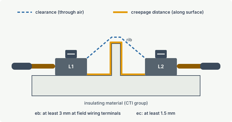
The required creepage distance depends on the working voltage and on the comparative tracking index (CTI) of the insulating material, which IEC 60079-7 groups in the same way as IEC 60664-1:
| Material group | CTI |
|---|---|
| I | 600 and above |
| II | 400 to below 600 |
| IIIa | 175 to below 400 |
| IIIb | 100 to below 175 |
Glass and ceramics do not track and count as group I. IEC 60079-7 gives no eb creepage values for material group IIIb, so it is not used for eb; only at 10 V and below is the CTI not relevant.
The table below shows a selection of minimum values from IEC 60079-7 (2015 edition). The standard lets the working voltage exceed the table voltage by a factor of 1.1, so 440 V equipment uses the 400 V row and 690 V equipment uses the 630 V row.
| Voltage up to (V r.m.s. or d.c.) | Creepage eb, group I (mm) | Creepage eb, group IIIa (mm) | Clearance eb (mm) | Clearance ec (mm) |
|---|---|---|---|---|
| 63 | 2.1 | 3.4 | 2.1 | 0.8 |
| 250 | 5.0 | 8.0 | 5.0 | 2.5 |
| 400 | 8.0 | 12.5 | 6.0 | 4.0 |
| 630 | 12 | 20 | 10 | 5.5 |
| 1 000 | 20 | 32 | 14 | 8.0 |
| 6 300 | 80 | 100 | 60 | 45 |
For field wiring terminals the minimum is never less than 3 mm (eb) or 1.5 mm (ec), even where the table gives a smaller value. The ec values apply to mains circuits and between isolated circuits; they do not apply to components mounted on printed boards. Spacings are checked with and without the conductor fitted, because a terminal with its clamp fully open can be the worst case.
Ribs and grooves count only if they are big enough: for eb, ribs at least 2.5 mm high and grooves at least 2.5 mm deep and wide; for ec, 1.5 mm. The certified distances also assume the conductor is fitted as specified: a strand left outside the clamp, or insulation stripped back too far, can reduce the clearance to the next terminal below the certified value.
Temperature limits
Two temperature rules apply to all Ex e equipment:
- No surface the gas can reach, including internal surfaces, may exceed the maximum surface temperature for the marked temperature class. See temperature classes T1 to T6.
- No insulating material may exceed the temperature its thermal endurance allows.
For windings the second rule is stricter than in industrial practice. A winding with thermal class 155 (F) insulation in an eb machine is limited to 130 °C in service (resistance method) and to 210 °C at the end of the tE time with the rotor locked.
Motors: the IA/IN ratio and the tE time
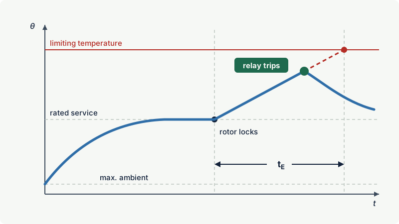
A cage induction motor has no brushes and no contacts; its risk is heat. If the rotor locks (a seized pump, a jammed conveyor), the motor draws its full starting current continuously, and rotor bars or winding can quickly reach the ignition temperature of the gas or damage the insulation. IEC 60079-7 handles this with two values marked on Ex eb motors protected by a current-dependent device:
- IA/IN, the ratio of the initial starting current to the rated current.
- tE, the time it takes the rotor or stator winding, carrying the starting current IA, to heat from its temperature in rated service at maximum ambient up to the limiting temperature. The limiting temperature is the lower of the temperature class limit and the limit set by the insulation.
The rules
- When a current-dependent device (for example a thermal overload relay) provides the protection, a stalled motor can in general be disconnected in time if tE is at least the minimum shown in the standard's curve for the motor's IA/IN. The curve falls from about 20 s at IA/IN = 3 to 5 s at IA/IN = 7 and above, because an overload relay trips faster at higher multiples of its setting. A tE below the curve is accepted only if a suitable protective device is specified and shown by test to be effective, and tE is in no case less than 5 s.
- IA/IN may not exceed 10.
- The overload device must disconnect a stalled motor within tE. The user should hold the device's time-current curve, giving the trip time from cold (20 °C ambient) for IA/IN of at least 3 to 8, with actual trip times within 20 % of the curve.
- Motors with arduous starting, where a correctly chosen relay would trip before the motor reaches rated speed, need other protection. The standard notes that this generally happens when the starting time exceeds 1.7 times tE.
- Where the motor is protected by embedded winding temperature sensors with an associated safety device (at least one sensor per phase), tE does not need to be determined and marked, but IA/IN still does.
- Motors fed by a converter must be tested with that converter or a comparable one, because harmonics and low-speed operation change the heating.
Air gap and rotor sparking
Ex e motors need a minimum radial air gap, from a formula that grows with rotor diameter and speed. Machines are also assessed for air gap sparking at start, using risk factors such as cage construction and voltage (for ec, only larger machines with certain duty types need this assessment). If the risk is too high, the motor must pass a starting test in an explosive mixture, be started only when shown to be free of gas (for example after pre-start ventilation), or have its starting current limited to 300 % of rated current.
Practical case: checking an overload relay
An Ex eb IIB T3 Gb pump motor has the following marking and data: IA/IN = 7.0, tE = 9 s. The run-up time with the pump load, measured at commissioning, is 4 s.
- Minimum tE. For IA/IN = 7 the standard's curve gives 5 s, so tE = 9 s lies above the curve and is suitable for protection by a current-dependent device.
- Relay curve. The overload relay's time-current curve gives a trip time from cold of 7 s at 7 times the set current, with a tolerance of 20 %. The worst case is therefore 8.4 s.
- Comparison with tE. 8.4 s is less than 9 s, so a stalled motor will be disconnected before the limiting temperature is reached.
- Starting. The run-up time of 4 s is well below the relay trip time, so the motor will start without nuisance tripping. It is also well below 1.7 × tE (15.3 s), so this is not an arduous start.
- Setting. The relay is set to the motor's rated current, not to a higher value "to stop it tripping". A higher setting moves the whole curve and can make the trip time at locked rotor longer than tE.
Had the relay curve given 11 s at IA/IN = 7, the arrangement would not be acceptable, even though the motor would run normally for years.
Ex eb vs Ex ec
Since the 2015 edition of IEC 60079-7, increased safety has two levels of protection. The former marking "e" became "eb", and the former non-sparking type "nA" from IEC 60079-15 became "ec". The comparison below summarises the main differences.
| Aspect | Ex eb | Ex ec |
|---|---|---|
| Equipment protection level | Gb (gas), Mb (mining) | Gc |
| Typical zone | Zone 1 (and Zone 2) | Zone 2 only |
| Former marking | e | nA (IEC 60079-15) |
| Maximum rated voltage | 11 kV | 15 kV |
| Semiconductors, electrolytic capacitors | Not within scope | Permitted |
| Minimum creepage and clearance at field wiring terminals | 3 mm | 1.5 mm |
| Motors | Locked rotor considered: IA/IN and tE marked, overload protection required | Steady rated operation is the normal condition; tE not required |
| Reduced spacings under conformal coating | Not permitted | Permitted on printed boards up to 1 100 V |
The logic is the same as for every EPL: eb must stay safe under the regular expected malfunctions, ec only in normal operation. An ec motor is not designed for a locked rotor in a gas cloud, and the standard notes that ec motors are not generally suitable where a gas release and a motor start can happen together. For more on Zone 2 equipment see Ex ec, Ex nA and Ex nR.
Junction boxes and terminal loading
An empty junction box produces no heat. The heat comes from the current in the terminals and, above all, in the cables inside, so the temperature class depends on what is installed. IEC 60079-7 therefore gives general purpose junction boxes a rating in one of two forms:
- Maximum dissipated power method. Tests with the worst-case terminal give the total power the box may dissipate within its temperature class. In service, the power of each circuit is calculated from its current and the resistance at 20 °C of the terminal (from its Ex Component certificate) and its conductor (length taken as half the internal diagonal of the box); the sum must not exceed the rating.
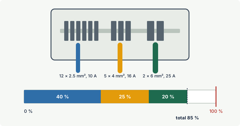
- Defined arrangement method. The manufacturer gives a table for a specific box size: for each conductor cross-section and current, the maximum number of conductors. Mixed loads are combined by adding the fraction of each permitted quantity used; the total must not exceed 100 %.
Worked example: utilisation of a junction box
A manufacturer's loading table for a particular Ex eb IIC T6 Gb box (the numbers here are illustrative, not from any real certificate) allows, among other combinations:
| Conductor | Current per conductor | Maximum conductors |
|---|---|---|
| 2.5 mm² | 10 A | 30 |
| 4 mm² | 16 A | 20 |
| 6 mm² | 25 A | 10 |
The planned installation is:
| Circuits | Conductors used | Permitted | Utilisation |
|---|---|---|---|
| Lighting, 2.5 mm² at 10 A | 12 | 30 | 40 % |
| Small motors, 4 mm² at 16 A | 5 | 20 | 25 % |
| Heater feed, 6 mm² at 25 A | 2 | 10 | 20 % |
| Total | 85 % |
At 85 % the box stays within T6. Six more 4 mm² conductors at 16 A would add 30 % and take the total to 115 %: the load would then have to be split, a larger box used, or a lower temperature class accepted if the certificate allows it. The counting rules (internal links, earth conductors) are stated with each table.
Practical rules for Ex e terminal boxes
- Use only terminals listed on the box certificate, in the permitted quantity and arrangement.
- One conductor per clamping point unless the terminal is certified for two; use the manufacturer's accessories for bridging.
- Tighten all screws to the specified torque, including those of unused terminals.
- Keep the stripped length within the terminal; no bare conductor should be visible outside the clamp.
- Use cable glands and stopping plugs that maintain the enclosure's IP rating and are certified for the type of protection. See cable glands for hazardous areas.
- Do not add components (relays, fuses, electronics) to an Ex e box unless the certificate covers them.
Enclosures and ingress protection
Because Ex e depends on clean insulation, the enclosure matters. IEC 60079-7 requires at least IP54 for enclosures containing bare live parts and IP44 where all live parts are insulated. Drain holes or ventilation openings may reduce this for Group II equipment, but not below IP44 and IP24 respectively, and then the certificate carries an "X" with the conditions. The rotor bars and end rings of a cage motor are not counted as bare live parts.
A cracked cover, a missing gasket or an open gland entry is therefore not just housekeeping in Ex e: it removes one of the conditions on which the creepage distances rely.
Common mistakes
- Putting a switch or contactor in an Ex e box. Anything that sparks in normal operation needs its own protection, normally Ex d, with an Ex e terminal compartment.
- Two conductors under one clamp. Unless the terminal is certified for it, the second conductor is not reliably held. Use a terminal of the correct size or a certified bridge.
- Filling a junction box "because the terminals fit". The temperature class depends on the total loading; check it against the rating table or the dissipated power.
- Setting the motor overload relay high to stop nuisance trips. This can make the trip time at locked rotor longer than tE. Investigate the starting conditions instead.
- Ignoring the IP rating after modification. A drilled entry without a certified gland, or a damaged gasket, reduces the protection the creepage distances depend on.
- Treating ec as interchangeable with eb. An ec motor or junction box is EPL Gc and belongs in Zone 2 only.
Frequently asked questions
What does Ex e mean on a nameplate?
e is the symbol for increased safety to IEC 60079-7. Modern equipment shows the level as eb (EPL Gb, suitable for Zone 1) or ec (EPL Gc, Zone 2), for example Ex eb IIC T6 Gb. Older equipment marked just e was built to editions before 2015 and corresponds to today's eb.
What is the tE time of an Ex e motor?
tE is the time in seconds that a winding takes, when carrying the starting current with the rotor locked, to heat from its full-load service temperature at maximum ambient to the limiting temperature. The motor's protective device must disconnect a stalled motor before tE elapses. tE is marked on the motor together with the starting current ratio IA/IN.
Can an Ex e enclosure be used in Zone 1?
Yes, if it is Ex eb (EPL Gb). Ex ec equipment is EPL Gc and is limited to Zone 2. In both cases the enclosure must contain only components that do not spark or overheat in normal operation and must keep its certified IP rating.
What is the difference between creepage and clearance?
Clearance is the shortest distance through air between two conductive parts; creepage distance is the shortest distance along the surface of the insulation between them. Clearance protects against flashover; creepage protects against tracking across contaminated surfaces. Ex e sets minimum values for both, depending on voltage and insulating material.
Is Ex e or Ex d better for a motor?
Neither is better in general. Ex eb motors are lighter and easier to maintain but need correctly coordinated overload protection, and their tE and IA/IN limit some applications. Flameproof motors tolerate arduous starting and contain internal faults, but need careful flamepath maintenance. See Ex d or Ex e.
Related on excodex
- Ex protection concepts at a glance
- Flameproof enclosures (Ex d)
- Ex d or Ex e? Choosing for motors and junction boxes
- Combined protection concepts: Ex db eb
- Ex ec, Ex nA and Ex nR: protection for Zone 2
- Tools: Ex marking check, forum, standards spaces IEC 60079-7 and IEC 60079-14
Standards and further reading
- IEC 60079-7, Explosive atmospheres: equipment protection by increased safety "e" (edition 5.1, 2015 with amendment 1 of 2017; a sixth edition is in preparation).
- IEC 60079-0, general requirements for Ex equipment.
- IEC 60079-14, design, selection and installation of electrical installations (sixth edition, 2024).
- IEC 60079-17, inspection and maintenance of electrical installations.
- IEC 60664-1, insulation coordination for low-voltage equipment (material groups and CTI).
- IEC 60034-1, rotating electrical machines: rating and performance (duty types S1 to S10).
- IEC webstore, IEC 60079-7:2015+AMD1:2017 consolidated version, abstract and scope: webstore.iec.ch
- IEC 60079-14:2024 preview with the table of significant changes: cdn.standards.iteh.ai
This article is general technical information prepared by the excodex editorial team. It does not replace the applicable standards, the equipment certificates and instructions, national regulations or the assessment of a competent person.