Flameproof enclosures (Ex d): how flamepaths stop an internal explosion
Abstract
A flameproof (Ex d) enclosure lets gas ignite inside, withstands the explosion pressure and cools the escaping gases in narrow flamepaths so the outside atmosphere does not ignite. Flamepath types, gaps, pressure piling and maintenance rules.
A flameproof enclosure (Ex d) does not try to keep the explosive gas out. It assumes the gas will get in and ignite, and it is built strong enough to withstand that internal explosion and to stop the flame from escaping. Every joint between parts of the enclosure is a flamepath: a gap so narrow and so long that the hot gases pushed through it lose their heat to the metal and leave too cool to ignite the atmosphere outside. Flameproof equipment at level db gives EPL Gb and is used mainly in Zone 1.
This article explains how flamepaths work, the different joint types (flanged, spigot, cylindrical and threaded), what decides the permitted gap and width, why pressure piling matters, and the installation and maintenance rules that keep an Ex d enclosure flameproof over its life.
Key points
- An Ex d enclosure must do two things: withstand the pressure of an internal explosion without damage, and prevent transmission of the explosion to the surrounding atmosphere through its joints.
- A flamepath is characterised by its gap (the clearance between the faces) and its width (the shortest path from inside to outside); the permitted gap gets smaller from IIA to IIB to IIC and depends on the joint type and the enclosure volume.
- Threaded flameproof joints need at least five full threads engaged, with a minimum axial engagement that depends on the enclosure volume.
- Enclosures are type tested at 1.5 times the measured explosion (reference) pressure, and this overpressure test is normally repeated on each production unit; the main exception is a design type tested at four times the reference pressure.
- Pressure piling, the pre-compression of gas in one part of an enclosure by an explosion in another, can create peak pressures far above normal; this is why internal components must not be added or rearranged.
- Flamepaths must stay clean, undamaged, ungasketed (unless the design includes a gasket), unpainted and protected against corrosion, with every bolt present and the obstruction distances respected.
The principle: let it ignite, but keep it inside
A flameproof enclosure is not gas-tight. Its joints are deliberately narrow but open, and the enclosure "breathes" as it warms and cools, so over time the gas inside will match the gas outside. Any spark from a contactor, a fault in a cable termination or a hot component can then ignite the mixture inside.
The design accepts this and relies on two properties:
- Strength. The walls, covers, windows and fasteners withstand the maximum pressure that the internal explosion can generate, with a safety factor proved by test.
- Non-transmission. Every route from inside to outside (cover joints, shaft passages, operating rods, cable entries, breathers) is a flamepath that stops the flame.
Because ignition inside is allowed, Ex d can house equipment that sparks in normal operation, such as switchgear, contactors, slip rings and high power circuits. The temperature class of a flameproof enclosure refers to its outer surface; the inside may be hotter.
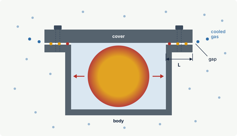
Level db (EPL Gb) is the normal flameproof level for Zone 1, and dc (EPL Gc) is a simplified level for Zone 2. A level "da" (EPL Ga) exists in IEC 60079-1, but the 2014 edition allows it only for catalytic sensors of portable combustible gas detectors, with a free internal volume of at most 5 cm³ and a supply from an intrinsically safe "ia" circuit.
How a flamepath stops the flame
When the gas inside ignites, the pressure rises within milliseconds and pushes burning gas and hot combustion products into every joint. Inside a narrow gap the flame is in close contact with two cold metal faces. The metal absorbs heat faster than the reaction can release it, and the reactive intermediate species that carry combustion are lost on the walls. The flame is quenched.
What leaves the outer edge of the joint is a jet of hot, partly burnt gas. If it is still too hot, or the jet carries enough energy, it can ignite the surrounding mixture as it mixes with it ("jet ignition"). The longer the path and the narrower the gap, the more heat is removed and the safer the exit gas.
The laboratory measure of this behaviour is the maximum experimental safe gap (MESG): the largest gap of a 25 mm wide joint that still prevents transmission of an explosion of a given gas. Hydrogen has a typical MESG of about 0.29 mm, ethylene 0.65 mm and propane 0.92 mm, which is the basis of gas groups IIC, IIB and IIA. Design gaps are smaller than the MESG to give a margin. For example, IEC 60079-1 allows a gap of up to 0.5 mm for a flanged joint at least 25 mm wide on a Group I (methane) enclosure, roughly half the MESG used for Group I firedamp in mines (about 1.14 mm; this mining value is not the one used for methane in group IIA); a 2005 comparison of IEC and US mining rules by the US Mine Safety and Health Administration (MSHA) describes this margin. See MESG and MIC and gas groups.
Gap and width
Two dimensions define every plane or cylindrical flamepath:
- Gap (i): the distance between the corresponding faces of the joint when the enclosure is assembled. For cylindrical joints it is the difference between the bore and shaft diameters.
- Width (L): the shortest path through the joint from the inside to the outside of the enclosure. Where bolt holes interrupt a flanged joint, the shortest path from the inside to the bolt hole (distance l) also has to meet a minimum value.
The surfaces also need a controlled finish: IEC 60079-1 limits the average roughness (Ra) of flamepath surfaces to 6.3 µm.
Flamepath types
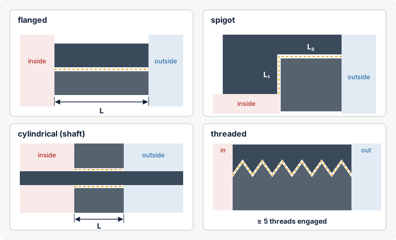
| Joint type | Where it is used | How it works | Practical notes |
|---|---|---|---|
| Flanged (plane) | Bolted covers and lids | Two flat machined faces clamped together by bolts | Gap can be checked with a feeler gauge; easily damaged by prying tools; bolt holes reduce the effective width |
| Spigot | Covers that locate with a turned spigot | A cylindrical part plus a plane part in series | Often carries an O-ring as a weather seal; the gap is not measurable once assembled |
| Cylindrical | Shafts, operating rods, spindles, push buttons | Narrow clearance between a shaft or rod and its bore | Wear increases the gap; bearings and replaceable bushes keep it within limits |
| Threaded | Screw-on covers, cable entries, glands, stopping plugs, sensor heads | Engaged threads form a long, tortuous path | At least five full threads engaged; minimum axial engagement depends on volume |
IEC 60079-1 also covers conical and serrated joints, cemented joints (for windows and some bushings, where the joint is filled with a cement that is tested as part of the enclosure) and breathing and draining devices, which use sintered or other flame-arresting elements. Serrated joints and some other special designs are accepted on the basis of specific tests set out in the standard.
Threaded joints in numbers
For parallel threaded joints, the standard requires a thread of suitable form and tolerance, at least five full threads engaged and a minimum axial length of engagement: 5 mm for enclosures up to 100 cm³ and 8 mm for larger ones (values of IEC 60079-1 as also summarised in the MSHA comparison; check the edition and the certificate for a specific product). The 2014 edition of IEC 60079-1 sets specific requirements for metric and NPT threaded entries, and fitting a gland or plug of one thread form into an entry of another is a serious error. A cover screwed in by only three turns is not flameproof.
What decides the permitted gap and width
IEC 60079-1 gives tables of the maximum gap for each minimum width, one table for Groups I, IIA and IIB and a separate one for IIC, each split by enclosure volume and joint type. Three rules run through those tables:
- More demanding gas, smaller gap. For the same width, IIB allows a smaller gap than IIA, and IIC is restricted further, with extra rules for flanged joints in acetylene atmospheres.
- Longer joint, larger permitted gap. A wider flamepath gives more cooling, so the gap may be somewhat larger.
- Larger enclosure, smaller permitted gap. Bigger volumes produce more forceful jets through the joints.
For a specific product, the binding values are on the manufacturer's certified drawings, not in the general tables. Inspectors who measure gaps compare them with the maximum stated by the manufacturer or with the standard's tables for that group and volume.
How the design is proved
Flameproof enclosures are type tested in two ways:
- Explosion pressure and overpressure tests. The enclosure is filled with the test gas mixture and ignited to determine the reference pressure, the highest pressure it generates. The enclosure must then withstand 1.5 times the reference pressure. This overpressure test is normally repeated on every production unit (routine test); the main exception is a design whose type test was done at four times the reference pressure (welded enclosures still need the routine test, and the standard also has a batch testing option).
- Non-transmission tests. The enclosure is filled with, and surrounded by, an explosive mixture, and internal ignitions are repeated. The tests use mixtures that pass flames more easily than the representative gas, or gaps enlarged beyond the design value, so that a safety factor is built in. The outside mixture must not ignite.
Pressure piling
If the inside of an enclosure is divided into compartments, or crowded with components that act like partitions, an ignition in one part pushes unburnt gas into the next part ahead of the flame. That gas is compressed before it burns. When the flame jets through the opening, it ignites an already pressurised, turbulent mixture, and the peak pressure in the second space can be much higher than the reference pressure of an open enclosure. This is pressure piling.
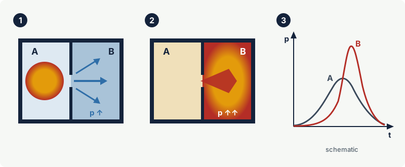
Manufacturers deal with pressure piling at the design and test stage: the internal arrangement is tested as built, interconnected compartments are avoided or made large enough, and walls between compartments are designed for the higher pressure. Studies of interconnected flameproof chambers have shown that the size of the connecting opening strongly influences the effect.
For users, the consequences are simple:
- Do not add components, partitions, extra terminal rails or spare cables inside a flameproof enclosure unless the manufacturer's documentation allows it.
- Do not connect two flameproof enclosures by an open conduit or pipe that was not certified as part of the assembly; use certified sealing devices where conduit systems are used.
- Replace internal parts only with the parts listed by the manufacturer.
Installation essentials
IEC 60079-14 sets the installation rules. For flameproof equipment the most important are:
- Cable entries. Use cable glands, thread adapters and stopping plugs certified for flameproof use (Ex db) and for the right thread. IEC 60079-14 gives a selection method that decides when a barrier (compound-filled) gland is needed, depending on the cable construction, the zone, the gas group and the enclosure. See cable glands for hazardous areas.
- Unused entries. Close them with certified flameproof stopping plugs, never with ordinary plastic dust caps or plugs from a different thread system.
- Obstruction of flanged joints. Solid objects close to a flanged joint can disturb the escaping gas and reflect it back. IEC 60079-1 gives minimum distances by gas group, and IEC 60079-14 applies them at installation: unless the certificate states otherwise (for example because the equipment was tested for a smaller distance), keep walls, steelwork, pipes, weather guards and other equipment at least 10 mm from the flange opening for IIA, 30 mm for IIB and 40 mm for IIC.
- Weather and corrosion protection. Protect flamepaths with non-setting grease or the inhibitor named by the manufacturer (see the maintenance rules below).
- Earthing and bonding. Connect the enclosure to the earthing and bonding system as for any metallic Ex equipment.
Maintenance and inspection rules
Most flameproof failures found in inspections are self-inflicted. IEC 60079-17 (inspection and maintenance) and IEC 60079-19 (repair) together give the following rules, paraphrased here:
- Isolate before opening. Never open a flameproof enclosure while it is energised in a hazardous area unless a gas-free permit and the site rules allow it. Some enclosures carry a warning to wait a stated time after switch-off before opening, so internal parts can cool.
- Protect the faces. Do not lever covers off with screwdrivers, do not lay a cover face-down on grit, and do not clean flamepaths with abrasive paper or wire brushes. Use the cleaning method in the instructions.
- Check for damage and corrosion. Scratches, dents and pitting across the width of a flamepath reduce its effective length. Light surface staining can usually be cleaned; deeper damage needs assessment against the manufacturer's data.
- Do not re-machine on site. Machining or re-facing a flamepath, or replacing a cover with a non-original part, is repair work under IEC 60079-19 and requires the manufacturer's dimensions and a competent repair facility.
- No sealants, tape or paint on the faces. Anything applied to a joint surface must not harden with age; hardening compounds, silicone sealants and paint can hold the joint open. Non-hardening grease-bearing tape wrapped around the outside of a flanged joint is tightly restricted by installation codes: at most a single layer, generally only in IIA atmospheres (some codes allow IIB only with very small gaps or the manufacturer's agreement), and never in IIC. Tests have shown that tape can markedly reduce the safe gap for IIB and IIC gases, so follow the equipment instructions and the code that applies.
- Every bolt, correct bolt. Missing bolts are among the most common findings. Replacements must have the same size, length and strength class as specified; a bolt that is too long can bottom in a blind hole and leave the cover loose.
- No modifications. Drilling a new entry, welding a bracket to the body, or fitting a window or push button that is not part of the certified design invalidates the protection.
- Keep the obstruction distances. New pipework, insulation or steelwork installed after commissioning often ends up against a flange.
Practical case: a corroded cover on a IIB junction box
During a close inspection at a coastal site, an inspector finds orange rust on the flanged joint of an Ex db IIB T4 Gb junction box. Two of the twelve cover bolts are missing and a cable entry is closed with a plastic cap.
- The circuit is isolated under the site permit, the cover is removed without levering on the faces, and the faces are cleaned with a non-metallic scraper and a solvent permitted by the instructions.
- The faces show shallow staining but no pitting across the width, so they can be reused.
- The faces are coated with non-setting grease, and the cover is refitted with all twelve bolts, the two missing ones replaced by bolts of the specified size, length and strength class. The gap, checked with a feeler gauge, is within the maximum on the manufacturer's documentation.
- The plastic cap is replaced with a certified flameproof stopping plug of the correct thread, and the record notes the corrosion and a shorter interval to the next close inspection.
Had the pitting run across the flamepath, the right action would have been replacement or repair to the manufacturer's dimensions by a competent facility, never filling the pits with compound.
Common mistakes
- Adding a gasket or silicone to stop water ingress. It can hold the joint open and is not part of the certified flamepath. Use the design's own seal, if any, and grease.
- Using an Ex e or industrial gland on an Ex d entry. The gland must be certified for flameproof use and the correct thread.
- Assuming any Ex d enclosure suits hydrogen. Only IIC (or IIB + H2) enclosures are tested for hydrogen; plain IIB is not enough.
- Fitting extra equipment inside "because there is space". It changes the free volume and can cause pressure piling and higher temperatures.
- Leaving bolts out because the cover "still seals". Every fastener is part of the strength and gap design.
- Installing the enclosure hard against a wall or beam. Respect the obstruction distances for the gas group.
Frequently asked questions
What is a flamepath in an Ex d enclosure?
A flamepath is any joint or gap through which gas can pass between the inside and outside of a flameproof enclosure, such as a cover flange, a shaft passage or a threaded cover. It is made narrow and long enough that an internal flame is cooled and quenched before it can reach the outside atmosphere.
Is "flameproof" the same as "explosion-proof"?
They follow the same principle: contain an internal explosion and prevent its transmission. "Flameproof" (Ex d) is the IEC and ATEX term, built to IEC 60079-1; "explosionproof" is the North American term for Class I Division equipment, built to standards such as UL 1203. The construction rules and test details differ, so one certification does not automatically satisfy the other.
Can I use a flameproof enclosure in Zone 0?
Normally not. Flameproof level db gives EPL Gb, suitable for Zone 1 and Zone 2. The level "da" for Zone 0 is limited by IEC 60079-1:2014 to catalytic sensors of portable gas detectors, so Zone 0 equipment normally uses intrinsic safety ia or encapsulation ma.
Can I drill an extra cable entry into an Ex d enclosure?
No, not on site. A new entry changes the certified design; it must be made by the manufacturer or under its documented instructions, with the correct thread form and depth, and recorded. Use an existing entry with a certified adapter where the certificate allows it.
Related on excodex
- Ex protection concepts at a glance
- Ex d or Ex e? Choosing between flameproof and increased safety
- Cable glands for hazardous areas
- Common Ex inspection findings and how to fix them
- Repair, overhaul and modification of Ex equipment (IEC 60079-19)
- Tools: Ex marking check, forum, standards space IEC 60079-1
Standards and further reading
- IEC 60079-1, Explosive atmospheres: equipment protection by flameproof enclosures "d" (an eighth edition was issued in 2026; check which edition a certificate refers to).
- IEC 60079-0, general requirements for Ex equipment.
- IEC 60079-14, design, selection and installation; IEC 60079-17, inspection and maintenance; IEC 60079-19, repair, overhaul and reclamation.
- ISO/IEC 80079-20-1, test methods for MESG.
- UL 1203, explosion-proof and dust-ignition-proof equipment (North America).
- IEC Electropedia, width of flameproof joint (IEV 426-06-05): electropedia.org
- IEC Electropedia, distance l of a flameproof joint interrupted by holes (IEV 426-06-07): electropedia.org
- US MSHA, Equivalency review and comparison of MSHA and IEC explosion-proof enclosure standards (2005, archived): webarchive.library.unt.edu
- IEC 60079-1 (2014) catalogue entry with scope and list of changes: standards.iteh.ai
- D. Li and S. Dai, numerical simulation of pressure piling in interconnected flameproof enclosures, Thermal Science, 2023: thermalscience.vinca.rs
This article is general technical information prepared by the excodex editorial team. It does not replace the applicable standards, the equipment certificates and instructions, national regulations or the assessment of a competent person.