MESG and MIC: the two test values behind gas groups IIA, IIB and IIC
Abstract
MESG is the widest 25 mm long gap that stops an internal explosion igniting the gas outside; the MIC ratio compares the smallest igniting spark current with methane's. How both tests work, the IIA, IIB and IIC limits, typical values and how mixtures are grouped.
The maximum experimental safe gap (MESG) and the minimum igniting current (MIC) ratio are the two laboratory values that put a flammable gas or vapour into gas group IIA, IIB or IIC. MESG is the widest gap, in a joint 25 mm long, between the two halves of a small test vessel that still stops an explosion inside from igniting the same mixture outside, at the most dangerous concentration. The MIC ratio is the smallest current that ignites the gas in the standard spark test apparatus (a 24 V circuit with a 95 mH coil), divided by the current that ignites methane. A gas is IIA with an MESG of 0.90 mm or more (MIC ratio above 0.80), IIB between 0.50 and 0.90 mm (MIC ratio 0.45 to 0.80) and IIC at 0.50 mm or less (MIC ratio below 0.45).
This article explains what each value measures, how the tests are done, why two values exist, where the group boundaries lie and which value decides near them, and how the values are used and misused.
Key points
- MESG measures how easily a flame is transmitted through a narrow gap; it is the physical basis of flameproof enclosures (Ex d). The MIC ratio measures how easily the gas is ignited by an electrical spark; it is the basis of intrinsic safety (Ex i).
- Both tests are defined in ISO/IEC 80079-20-1 (2017), which replaced IEC 60079-20-1. MESG is measured in a 20 cm³ spherical chamber with a 25 mm wide flange gap inside a larger chamber, at 20 °C and 101.3 kPa.
- MIC is measured with the spark test apparatus of IEC 60079-11 in a 24 V d.c. circuit with a (95 ± 5) mH air-cored coil, at the most easily ignited concentration.
- Typical values: hydrogen 0.29 mm and 0.25, acetylene 0.37 mm and 0.28, ethylene 0.65 mm and 0.53, propane 0.92 mm and 0.82; methane has an MESG of about 1.12 mm (1.14 mm in the firedamp entry for Group I) and is the MIC reference (ratio 1).
- One value is enough for most substances. Near a boundary both are measured: the MIC ratio decides when the MESG is between 0.50 and 0.55 mm, the MESG decides when the MIC ratio is between 0.70 and 0.90 or between 0.40 and 0.50.
- MESG is not a design gap. Flameproof joints are built with much smaller gaps, and the MESG itself falls as temperature and pressure rise.
Why two test values?
Explosion protection by enclosure and explosion protection by energy limitation work in completely different ways, so they need different measures of how "dangerous" a gas is:
- A flameproof enclosure lets the gas in, accepts that it may ignite inside, and relies on narrow, long joints (flamepaths) to cool the escaping gases so they cannot ignite the atmosphere outside. What matters is how small a gap must be to stop a flame of that gas. That is the MESG.
- An intrinsically safe circuit prevents ignition in the first place by keeping the energy of any spark too low. What matters is how small a spark can ignite the gas. That is the MIC ratio.
Both properties reflect the same underlying chemistry (how fast and how hot the gas burns), so they correlate well: gases with a small MESG also tend to have a low MIC ratio. They are not identical, though, which is why the classification rules say when one value is enough and when both are needed. The same gas groups then apply to all types of protection; for those that rely on neither principle, the group still matters for secondary requirements such as electrostatic limits on plastic enclosures (see gas groups IIA, IIB and IIC).
The MESG test
History in one paragraph
The idea is as old as mining safety lamps: early nineteenth-century lamps used gauze or narrow channels to stop flames. An HSE review of MESG methods records that the first research on explosion transmission from electrical machines in coal mines found that a gap of 1.2 mm between 50 mm flanges stopped methane explosions. UK researchers later standardised 25 mm (1 inch) flanges in an 8 litre sphere, and German laboratories developed the 20 ml (20 cm³) vessel that became the international method. For most gases the two European vessels give similar values; a North American apparatus with a small, closed receiving chamber gave very different results for some gases (for diethyl ether about 0.3 mm against 0.87 mm), which the same review attributes to the confinement of the outer mixture. Today's standard apparatus is designed to represent ignition of an open, unconfined cloud.
The apparatus
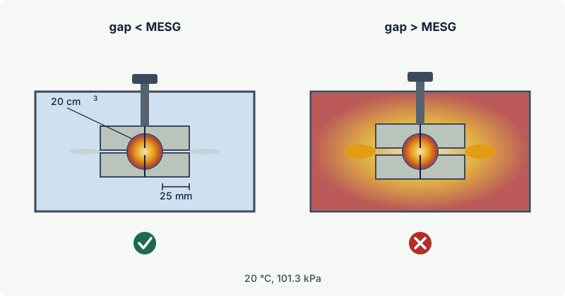
ISO/IEC 80079-20-1 describes the apparatus (paraphrased):
- an inner chamber: a sphere of 20 cm³ (about 34 mm diameter), split horizontally into two halves whose flat rims form a joint 25 mm wide;
- an outer chamber: a cylinder 200 mm in diameter and 75 mm high around it, with windows for observation;
- a micrometer that sets the gap between the two rims precisely;
- spark electrodes in the inner chamber, with the spark path perpendicular to the plane of the joint;
- a construction strong enough (designed for 1 500 kPa) that the joint does not spring open during the internal explosion, normally in stainless steel, with flame arresters on the gas inlet and outlet.
Both chambers are filled with the same gas-air mixture, at 20 °C and 101.3 kPa. Substances whose vapour pressure is too low to make the required mixture at 20 °C are tested hotter: the standard specifies 5 K above the temperature needed for the vapour pressure, or 50 K above the flash point.
The procedure
- Preliminary series. For one concentration, two ignitions are made at each gap, in steps of 0.02 mm, from a gap that never transmits to one that always transmits. This gives g0, the largest gap with no external ignition, and g100, the smallest gap at which every test transmits.
- Concentration sweep. The series is repeated over a range of concentrations. The "most dangerous mixture" is the one with the smallest g0 and g100. It is usually close to the stoichiometric mixture: the tabulated data give about 4.2 % for propane, 6.5 % for ethylene and 27 % for hydrogen.
- Confirmation. Around that concentration, 10 ignitions are made at each gap step. The smallest g0 is the MESG.
- Reproducibility. Different test series should agree within 0.04 mm. The tabulated g100 minus g0 indicates the precision, typically one gap step (0.02 mm). The apparatus itself is checked regularly with reference gases.
External ignition is judged by eye: the outer chamber must be seen to fill with flame. A test without internal ignition is invalid.
What happens in the gap
The flame itself does not "squeeze through" the gap. When the inner mixture burns, pressure rises within milliseconds and pushes hot combustion products through the joint. Inside the narrow gap the gas loses heat to the two metal faces; at the exit it forms a turbulent jet that mixes with the cold outer mixture. If the jet is still hot enough and contains enough reactive species when it meets fresh mixture, it re-ignites it. If the gap is narrow, the jet arrives too cool and too diluted. MESG is the largest gap at which the outcome is reliably "no ignition".
Because this is a heat and mixing process, MESG depends on the conditions. The standard's data annex notes that MESG decreases with increasing temperature and pressure. It is a property of a gas at atmospheric conditions, measured in one specific geometry, not a universal constant.
The MIC test
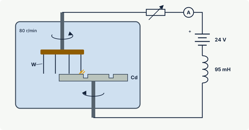
The minimum igniting current is defined as the smallest current in a resistive or inductive circuit that ignites the test mixture in the spark test apparatus of IEC 60079-11. The apparatus is the same one used to test intrinsically safe circuits:
- A cadmium disc with two slots and an electrode holder with four tungsten wires (0.2 mm diameter) rotate on two offset shafts inside an explosion chamber of at least 250 cm³.
- The holder turns at 80 revolutions per minute and the disc more slowly in the opposite direction, so the wires repeatedly touch, slide over and leave the disc and its slots, producing make and break sparks.
- For MIC, the contacts are connected in a 24 V d.c. circuit with a (95 ± 5) mH air-cored coil. When the circuit breaks, the coil drives a spark across the opening contact.
- The current is reduced until ignition of the most easily ignited concentration of the gas just still occurs. That current is the MIC.
The MIC ratio is the MIC of the gas divided by the MIC of laboratory methane measured the same way. Expressing the result as a ratio makes results from different laboratories easier to compare.
For certification testing, the same apparatus is calibrated with representative mixtures. IEC 60079-11 specifies 8.3 % methane (Group I), 5.25 % propane (IIA), 7.8 % ethylene (IIB) and 21 % hydrogen (IIC), and the calibration currents in the 24 V, 95 mH circuit fall from about 110 mA for methane through 100 mA and 65 mA to about 30 mA for hydrogen. These are sensitivity checks of the apparatus, not MIC values, but they show the scale of the difference between the groups.
Note: The MIC ratio is not the same as the minimum ignition energy (MIE). MIE is measured with capacitive spark discharges and expressed in millijoules; it is used mainly for electrostatic hazards. MIC uses inductive break sparks and is expressed as a ratio. See flash point, autoignition temperature and minimum ignition energy.
Group boundaries and which value decides
| Group | MESG | MIC ratio | Representative gas |
|---|---|---|---|
| IIA | 0.90 mm or more | above 0.80 | propane |
| IIB | above 0.50 mm and below 0.90 mm | 0.45 to 0.80 | ethylene |
| IIC | 0.50 mm or less | below 0.45 | hydrogen |
ISO/IEC 80079-20-1 allows classification on either value for most substances, but asks for both near the boundaries, and then says which one decides:
- MESG between 0.50 and 0.55 mm: both are measured, and the MIC ratio decides the group.
- MIC ratio between 0.70 and 0.90, or between 0.40 and 0.50: both are measured, and the MESG decides.
Where neither value has been measured, a substance can be classified provisionally by chemical similarity, from lower members of the same homologous series. Tables mark such entries; treat them with appropriate caution.
Typical values
The table gives values from the data annex of the IEC material characteristics standard (2010 edition, the basis of ISO/IEC 80079-20-1), with the group used in the excodex library.
| Substance | MESG (mm) | MIC ratio | Group |
|---|---|---|---|
| Ammonia | 3.18 | not listed | IIA |
| Methane | 1.12 (1.14 as firedamp) | 1 (reference) | IIA (Group I in mines) |
| n-Butane | 0.98 | 0.94 | IIA |
| n-Pentane | 0.93 | 0.97 | IIA |
| Propane | 0.92 | 0.82 | IIA |
| Ethane | 0.91 | 0.82 | IIA |
| Ethanol | 0.89 | 0.88 | IIB |
| Diethyl ether | 0.87 | 0.88 | IIB |
| Carbon monoxide | 0.84 | not listed | IIB |
| Hydrogen sulphide | 0.83 | not listed | IIB |
| Ethylene | 0.65 | 0.53 | IIB |
| Ethylene oxide | 0.59 | 0.47 | IIB |
| Acetylene | 0.37 | 0.28 | IIC |
| Carbon disulphide | 0.34 | 0.39 | IIC |
| Hydrogen | 0.29 | 0.25 | IIC |
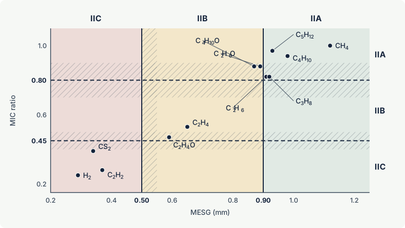
A few entries deserve comment:
- Ethanol and diethyl ether show why the rules exist. Their MIC ratio of 0.88 is above the IIA limit, but it falls in the 0.70 to 0.90 range where the MESG decides, and their MESG is just below 0.90 mm: they are IIB. The 2017 edition adds a second entry for ethanol: in air containing at least 4 % water vapour it is IIA, while dry ethanol stays IIB.
- Carbon monoxide is tabulated for air saturated with moisture. Moisture and small amounts of hydrocarbons speed up its combustion and lower its MESG, so the IIB classification covers realistic conditions; drier mixtures give a larger gap.
- Ammonia has a very large MESG (3.18 mm) because its flames are slow and cool. It is IIA with a wide margin, though its narrow flammable range and toxicity bring other problems.
- Acetylene gives scattered results. An HSE review notes that it often behaves like hydrogen (about 0.3 mm), but that decomposition reactions have produced external ignition at gaps too small to measure. This is one reason why acetylene has extra restrictions in some protection concepts (see the special cases of group IIC).
Mixtures of gases
A mixture should ideally be tested. As an estimate, the data standard gives a Le Chatelier-type rule: the reciprocal of the mixture MESG is the sum of each component's mole fraction divided by its MESG. The method is not to be used for mixtures containing acetylene, oxygen or another strong oxidiser, or more than 5 % carbon monoxide, and the standard gives conventions for inert components such as nitrogen.
Example: A process gas of 80 % propane (0.92 mm) and 20 % ethylene (0.65 mm): 1 / (0.8 / 0.92 + 0.2 / 0.65) = 0.85 mm. The mixture is IIB, although propane dominates. A 50/50 mixture of methane (1.12 mm) and propane gives 1.01 mm: two IIA gases stay IIA, which the standard also states for methane mixed with other IIA substances in any proportion.
The rule is an approximation and can be conservative. For methane with 10 % hydrogen it gives 0.87 mm (IIB), whereas the data standard (2010 and 2017 editions) states that industrial methane such as natural gas remains IIA if it contains no more than 25 % hydrogen by volume. For hydrogen blends and other unusual compositions, use measured data or the current edition of the standard. Choosing the group for mixtures is covered in mixtures of flammable gases and vapours.
How the values are used, and how not
Used for: assigning a substance to IIA, IIB or IIC; that group then appears in area classification documents and decides which equipment marking is acceptable. Equipment standards translate the groups into design rules: permitted flamepath gaps in IEC 60079-1, and permitted voltage, current, capacitance and inductance in IEC 60079-11.
Not used as: a design or inspection value. Flameproof joints are designed well below the MESG, with the margin built into the tables of IEC 60079-1 and confirmed by non-transmission tests with more searching mixtures. For Group I, for example, a flanged joint at least 25 mm wide may have a gap of up to 0.5 mm, against an MESG of about 1.14 mm for firedamp. A flamepath gap measured on site is compared with the certificate and manufacturer's data, never with the MESG of the gas.
Not valid at other conditions: MESG and MIC are measured in air at atmospheric pressure and about 20 °C. At elevated pressure or temperature, or with oxygen enrichment, flames pass smaller gaps and sparks ignite at lower currents. Equipment certified for a gas group covers atmospheric conditions only (see oxygen concentration, enrichment and inerting).
Worked example: classifying a new solvent
A plant introduces a solvent not found in the usual tables. The supplier's laboratory reports an MIC ratio of 0.85.
- One value or two? 0.85 lies between 0.70 and 0.90, so an MIC ratio alone is not enough; the MESG must be measured and will decide.
- MESG result: 0.88 mm. That is below 0.90 mm, so the solvent is IIB, even though its MIC ratio is above the IIA limit of 0.80.
- Consequence for equipment: IIB or IIC equipment is required. A IIA flameproof motor or a IIA intrinsically safe loop would not be acceptable.
- Temperature class: chosen separately from the autoignition temperature.
This is exactly the situation of ethanol and diethyl ether in the table above. Had the laboratory reported only the MIC ratio, the solvent would have been wrongly placed in IIA.
Common mistakes and misconceptions
- Treating the MESG as the permitted flamepath gap. Design gaps in IEC 60079-1 are much smaller than the MESG; always use the certificate and manufacturer's data.
- Reading a large MESG as "less flammable". MESG says nothing about flammable limits, flash point or autoignition temperature. Ammonia has the largest MESG in the table but is toxic and flammable; carbon disulphide is IIC but needs T6.
- Classifying near a boundary on one value. In the overlap ranges both values are required, and the rules say which decides.
- Confusing MIC with MIE, or mixing data from different apparatus. MIC and MIE come from different tests and cannot be converted into each other; safe gaps from non-standard apparatus can differ greatly from the standard method.
- Extrapolating to process conditions. MESG decreases with higher temperature and pressure; certified equipment is not tested for pressurised or oxygen-enriched atmospheres.
Frequently asked questions
What is the maximum experimental safe gap (MESG)?
It is the largest gap between the two halves of a 20 cm³ test chamber, with a 25 mm long joint, that prevents an internal explosion from igniting the same gas mixture surrounding the chamber, at the most dangerous concentration and at atmospheric conditions. It is measured according to ISO/IEC 80079-20-1 and used to assign gases to groups IIA, IIB and IIC.
What is the MESG of hydrogen?
About 0.29 mm in the IEC data tables, one of the smallest of any common gas; acetylene (0.37 mm) and carbon disulphide (0.34 mm) are similar. All three are in group IIC, which covers gases with an MESG of 0.50 mm or less.
What is the MIC ratio?
It is the minimum current that ignites a gas in the IEC 60079-11 spark test apparatus, in a 24 V circuit with a 95 mH coil, divided by the minimum igniting current of laboratory methane. A ratio above 0.80 means IIA, 0.45 to 0.80 IIB, and below 0.45 IIC.
Why is methane the reference for the MIC ratio?
Methane was the gas for which explosion protection was first developed, in coal mines, and it remains the reference gas of Group I. Using it as the denominator turns an apparatus-dependent current into a ratio that laboratories can compare.
Which value decides if MESG and MIC ratio disagree?
The standard gives the rule. If the MESG is between 0.50 and 0.55 mm, the MIC ratio decides; if the MIC ratio is between 0.70 and 0.90 or between 0.40 and 0.50, the MESG decides. Outside these ranges one value is enough.
Related on excodex
- Gas groups IIA, IIB and IIC explained with typical gases
- Flameproof enclosures (Ex d): how flamepaths stop an internal explosion
- Intrinsic safety (Ex i): ia, ib and ic and the energy limitation principle
- IIB+H2 explained: when is it enough for hydrogen?
- How to find the gas group and temperature class of a substance
- Gas library with groups: /gas; standards spaces ISO/IEC 80079-20-1, IEC 60079-1 and IEC 60079-11; Ex marking check
Standards and further reading
- ISO/IEC 80079-20-1:2017, Explosive atmospheres, material characteristics for gas and vapour classification, test methods and data (replaced IEC 60079-20-1:2010; catalogue entry with preview): https://standards.iteh.ai/catalog/standards/iec/1bf4ec16-63c8-413f-9547-99bad8173a93/iso-iec-80079-20-1-2017
- IEC 60079-20-1:2010 as adopted by the Bureau of Indian Standards (test method and data annex quoted in this article): https://law.resource.org/pub/in/bis/S05/is.iec.60079.20.1.2010.pdf; IEC webstore (current edition, ISO/IEC 80079-20-1:2017): webstore.iec.ch
- IEC 60079-11, equipment protection by intrinsic safety "i" (spark test apparatus; current edition 7.0, 2023). Public copy of the 2011 edition used for the apparatus description: https://law.resource.org/pub/us/cfr/ibr/inc/iec/iec.60079-11.2011.pdf; IEC webstore (current edition, IEC 60079-11:2023): webstore.iec.ch
- IEC 60079-1, equipment protection by flameproof enclosures "d".
- H. Phillips (HSE), A comparison of "standard" methods for the determination of maximum experimental safe gap (MESG): https://stacks.cdc.gov/view/cdc/185612/cdc_185612_DS1.pdf
This article is general technical information prepared by the excodex editorial team. It does not replace the applicable standards, the equipment certificates and instructions, national regulations or the assessment of a competent person.