Intrinsic safety (Ex i): ia, ib and ic and the energy limitation principle
Abstract
Intrinsic safety (Ex i) limits the energy in a circuit so that no spark or hot surface can ignite the gas, even with faults. How ignition curves work, what ia, ib and ic mean, and the roles of simple apparatus, associated apparatus and cable parameters.
Intrinsic safety (Ex i) is a type of protection that limits the electrical energy in a circuit, both the energy released in a spark and the heating of any surface, to a level too low to ignite the surrounding explosive atmosphere. The limit must hold in normal operation and with faults: two countable faults for level ia (EPL Ga, suitable for Zone 0), one for ib (EPL Gb, Zone 1) and none for ic (EPL Gc, Zone 2). Because safety depends on the whole circuit, Ex i is a system concept: the field device, the associated apparatus that limits the energy, and the cable between them are assessed together.
This article explains the energy limitation principle, how ignition curves are produced and used, what separates ia, ib and ic, and the roles of intrinsically safe apparatus, associated apparatus, simple apparatus and the cable.
Key points
- An intrinsically safe circuit cannot ignite the gas by a spark when it is opened, shorted or earthed, nor by a hot surface, in normal operation and under the faults defined for its level of protection.
- Ignition limits come from the spark test apparatus run in standard test mixtures: 21 % hydrogen for IIC, 7.8 % ethylene for IIB, 5.25 % propane for IIA and 8.3 % methane for Group I.
- Levels ia and ib apply a safety factor of 1.5 to current or voltage in the spark assessment (ia with two faults is assessed at 1.0); level ic is assessed in normal operation with a factor of 1.0.
- Associated apparatus (barriers, isolators, IS power supplies) contains the energy-limiting circuit and is marked with square brackets, for example
[Ex ia Ga] IIC; it is installed in the non-hazardous area unless it has another type of protection. - Simple apparatus, such as switches, thermocouples, RTDs and junction boxes, needs no certificate but must meet the definition in IEC 60079-11 and be included in the system assessment.
- The cable stores energy too: its capacitance and inductance, plus those of the field device, must stay within the Co and Lo allowed by the associated apparatus.
The principle: too little energy to ignite
Every flammable gas or vapour needs a minimum amount of energy to ignite. An electrical circuit can release energy in two ways: as a spark when a conductor breaks, closes or touches earth, and as heat in a component or wire. Intrinsic safety limits both.
Three sources feed a spark:
- the power source, limited by its open-circuit voltage and short-circuit current;
- capacitance in the circuit, which stores energy that is dumped into a short circuit almost instantly;
- inductance, which stores energy in its magnetic field and releases it as an arc when the current is interrupted.
An intrinsically safe design keeps all three below the ignition limits, with a margin. In practice the available power is small: a typical source of 28 V and 93 mA can deliver at most about 0.65 W into a matched load. That is enough for transmitters, sensors, solenoid valves designed for low power, and signalling, but not for motors or heaters.
The low energy brings advantages no other concept offers in the same way. There is no heavy enclosure, the equipment can be used in Zone 0, and IEC 60079-17 contains provisions for live maintenance on intrinsically safe installations, so instruments can be checked or replaced without first making the area gas-free, where the site rules allow it.
Ignition curves: how much is too much
The spark test apparatus
The ignition limits in IEC 60079-11 come from tests with a standard spark test apparatus: a rotating cadmium disc and tungsten wires that make and break the circuit repeatedly inside a chamber filled with a defined explosive mixture. The mixtures are chosen to be easy to ignite for each group:
| Group | Test mixture in air | Typical gas group member |
|---|---|---|
| I | 8.3 % methane | Mining |
| IIA | 5.25 % propane | Propane, many hydrocarbons |
| IIB | 7.8 % ethylene | Ethylene |
| IIC | 21 % hydrogen | Hydrogen, acetylene, carbon disulphide |
Repeating the test over a range of voltages, currents, capacitances and inductances produces the reference ignition curves (and tables) in the standard:
- Resistive circuits: the minimum igniting current against the open-circuit voltage, for a source with a series current-limiting resistor.
- Capacitive circuits: the minimum igniting voltage against capacitance.
- Inductive circuits: the minimum igniting current against inductance. For large inductances the curves approach a constant spark energy, quoted in the standard as 40 µJ for IIC, 160 µJ for IIB, 320 µJ for IIA and 525 µJ for Group I.
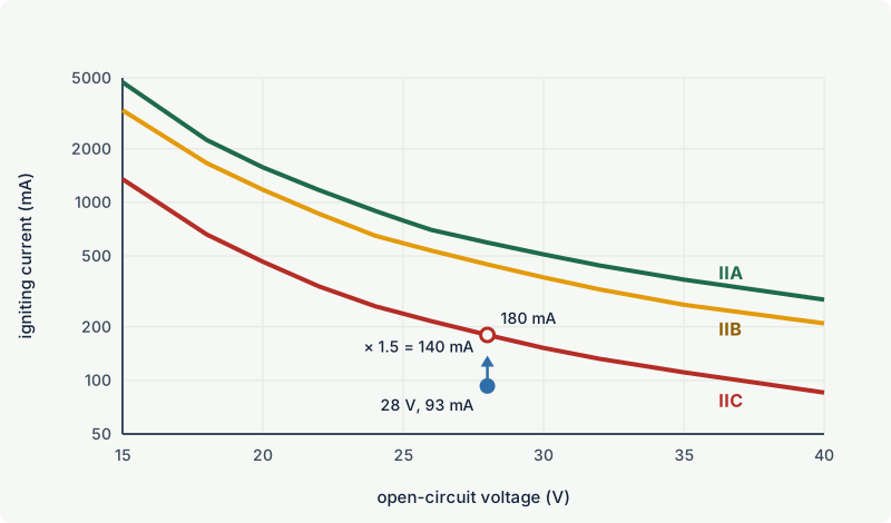
Using the curves
A designer first finds the worst case (highest voltage, lowest resistance, component tolerances, the faults required for the level), then applies the safety factor, then checks the result against the curve. The 28 V source in the figure works like this:
- Worst-case open-circuit voltage 28 V, minimum series resistance 300 Ω, so a short-circuit current of 93 mA.
- For ia or ib the current is multiplied by 1.5: 140 mA.
- The IIC resistive curve allows 180 mA at 28 V. 140 mA is below it, so the source is acceptable for IIC with respect to spark ignition of the source itself.
The same voltage limits the capacitance that may be connected. The table below shows a few values from IEC 60079-11 with the 1.5 safety factor included; it explains why IIC circuits allow much less cable than IIB or IIA circuits.
| Group | Permitted current at 24 V, resistive (mA) | Permitted capacitance at 28 V (µF) |
|---|---|---|
| IIC | 174 | 0.083 |
| IIB | 433 | 0.65 |
| IIA | 597 | 2.15 |
The curves only describe simple linear circuits: a battery or supply behind a resistor, a single capacitor, a single inductor. Non-linear supplies, such as constant-current sources, can ignite at much lower currents than the resistive curve suggests; the standard warns that in some cases only about one fifth of the curve value is safe. Such circuits are tested on the spark test apparatus rather than assessed from curves.
Thermal ignition
The second route to ignition is a hot surface. Every component and wire the gas can reach must stay within the temperature class under the fault conditions of the level, with a factor of 1.0. IEC 60079-0 and IEC 60079-11 give simplified rules for small parts; the one used most in practice is that a component with a surface area of at least 20 mm² may be classed T4 if the power it can dissipate does not exceed 1.3 W at a maximum ambient of 40 °C (1.2 W at 60 °C, 1.0 W at 80 °C).
Levels of protection: ia, ib and ic
IEC 60079-11 defines three levels of protection. They differ in how many faults the circuit must survive and in the safety factor applied.
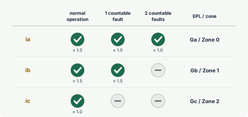
| Level | Must not ignite | Spark safety factor | EPL | Typical zones |
|---|---|---|---|---|
| ia | In normal operation, with one countable fault, and with two countable faults | 1.5 (normal and one fault), 1.0 (two faults) | Ga | 0, 1, 2 |
| ib | In normal operation and with one countable fault | 1.5 | Gb | 1, 2 |
| ic | In normal operation and under the conditions specified in the standard | 1.0 | Gc | 2 |
Countable and non-countable faults
A countable fault is a fault in a part that is built to the constructional requirements of the standard: a component used within two thirds of its rating, a separation that meets the creepage, clearance and insulation tables, an encapsulation that follows the rules. Faults in parts that do not meet these requirements are non-countable: they are simply assumed to happen, as often as is most onerous, and do not use up the fault allowance.
Some parts are treated as infallible: a correctly rated and mounted current-limiting resistor, a safety transformer built to the standard, a properly constructed shunt diode assembly, or a separation that meets the infallible requirements. These are not considered to fail in the dangerous way. That is how a barrier achieves ia: its resistor is infallible, and its voltage-limiting diodes form at least two parallel paths, so that the failure of one still leaves another in place, and the diodes are routine tested.
Level ic, which replaced the former energy-limited type of protection "nL", does not use the concept of countable faults or infallible components. The 2023 edition of IEC 60079-11 clarified which fault conditions are nevertheless considered for ic in the spark assessment and in setting the output and input parameters, so check the edition named on the certificate.
Which level, which group
The level and the group are independent. A circuit can be ia IIB or ib IIC. The group follows the gas (see gas groups IIA, IIB and IIC): IIC equipment may be used in IIB and IIA atmospheres, and the reverse is not allowed. The level follows the zone through the EPL (see EPLs and zones). An intrinsically safe circuit takes the lowest level of any part in it: an ia field device on an ib barrier forms an ib circuit.
The parts of an intrinsically safe system
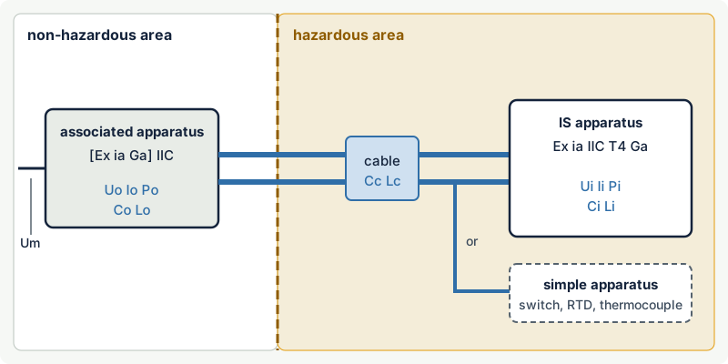
Intrinsically safe apparatus
Field devices in which all circuits are intrinsically safe: transmitters, sensors, valve positioners, intrinsically safe gas detectors. They carry a normal Ex marking such as Ex ia IIC T4 Ga and list their input parameters: the maximum voltage Ui, current Ii and power Pi that may be applied to their terminals without loss of safety, and their internal capacitance Ci and inductance Li as seen at the terminals.
Associated apparatus
Apparatus that contains both intrinsically safe and non-intrinsically safe circuits, built so that the non-intrinsically safe side cannot affect the intrinsically safe side. Typical examples are zener barriers, galvanic isolators and intrinsically safe power supplies; a gas detector controller with intrinsically safe sensor outputs is also associated apparatus. Its marking puts the Ex i part in square brackets:
[Ex ia Ga] IIC(ATEX category shown asII (1) G): installed in the non-hazardous area, provides ia circuits.Ex db [ia Ga] IIC T4 Gb: flameproof enclosure in Zone 1 containing associated apparatus that feeds ia circuits.
Associated apparatus declares output parameters: Uo, Io, Po, the maximum external capacitance Co and inductance Lo it may be connected to, often Lo/Ro, and Um, the highest voltage that may be applied to its non-intrinsically safe terminals without invalidating the protection (commonly 250 V). The comparison of these with the field device and cable is explained in loop verification. The choice between barriers and isolators is covered in zener barriers vs galvanic isolators.
Simple apparatus
Some field devices are so simple that they can neither store significant energy nor generate it. IEC 60079-11 treats the following as simple apparatus:
- passive components, such as switches, junction boxes, resistors (including RTDs) and simple semiconductor devices such as LEDs;
- single energy-storing components with well-defined values, such as a capacitor or inductor, whose values are included in the system assessment;
- energy-generating components that produce no more than 1.5 V, 100 mA and 25 mW, such as thermocouples and photocells.
Simple apparatus needs no certificate and no Ex marking, but it must still comply with the relevant requirements: no voltage or current limiting devices to achieve safety, no voltage multiplication, enclosure materials that avoid electrostatic hazards, and insulation that withstands 500 V to earth if the circuit relies on being isolated. Switches, plugs, sockets and terminals used within their rating at up to 40 °C ambient may be classed T6; other simple apparatus is usually classed T4 by the 1.3 W rule above. The 2024 edition of IEC 60079-14 added a normative annex on simple apparatus and lists it as a major technical change, so check the current installation requirements before relying on older practice.
Cable parameters
The cable between associated apparatus and field device is part of the circuit. Each metre adds capacitance between the cores and inductance around the loop, and both store energy that the curves must allow for. The basic conditions are:
- total capacitance: Ci of the field devices plus the cable capacitance Cc must not exceed Co;
- total inductance: Li plus the cable inductance Lc must not exceed Lo, or, where Li is negligible, the cable's inductance to resistance ratio Lc/Rc must not exceed Lo/Ro.
Cable data should come from the cable manufacturer or from measurement. Where it is not available, IEC 60079-25 allows conservative values for ordinary two- or three-core cable of 200 pF/m and 1 µH/m. With the IIC value of 83 nF for a 28 V source and a field device with negligible Ci, that would allow roughly 400 m of cable by capacitance alone. Long runs in IIC are therefore often limited by the cable, not by the instrument.
Intrinsically safe cables also have installation rules: they are kept separate from non-intrinsically safe cables, clearly identified (a light blue colour is widely used for this), and their terminals are separated from non-intrinsically safe terminals by at least 50 mm or by a partition. Terminals of separate intrinsically safe circuits are at least 6 mm apart. Each circuit must be either isolated from earth or earthed at one point only.
Common mistakes
- Treating a certified field device as safe on its own. An
Ex iatransmitter is only intrinsically safe when it is connected to suitable associated apparatus through a cable within the permitted parameters. - Connecting a non-certified power supply directly to an IS device. Without associated apparatus nothing limits the energy; the circuit is not intrinsically safe however low its normal voltage.
- Assuming simple apparatus needs no assessment. It needs no certificate, but its temperature class, its insulation to earth and any capacitance or inductance must be documented in the system assessment.
- Mixing up the levels. An ia device on an ib barrier makes an ib circuit, which is not acceptable in Zone 0.
- Ignoring the gas group in cable length calculations. Co and Lo for IIC are much smaller than for IIB; a cable that was acceptable in a IIB plant may not be in a IIC one.
- Bringing other circuits into the IS cable or terminals. Non-IS conductors in the same multicore or terminal row can inject energy and defeat the protection.
Frequently asked questions
What is the difference between Ex ia, Ex ib and Ex ic?
All three limit energy, but they differ in fault tolerance. Ex ia remains safe with two countable faults and is suitable for Zone 0 (EPL Ga); Ex ib remains safe with one fault and suits Zone 1 (EPL Gb); Ex ic is safe in normal operation and is limited to Zone 2 (EPL Gc). Levels ia and ib also apply a 1.5 safety factor in the spark assessment.
Why is intrinsic safety allowed in Zone 0?
Because level ia stays safe even with two independent faults and a safety margin, the probability that it becomes an ignition source at the same time as an explosive atmosphere is present is extremely low. That matches EPL Ga, the protection level required for Zone 0.
What does the square bracket in [Ex ia] mean?
Square brackets identify associated apparatus: equipment that provides an intrinsically safe circuit to the hazardous area but is itself not intrinsically safe. [Ex ia Ga] IIC equipment must be installed in the non-hazardous area, unless the marking shows another type of protection outside the brackets, such as Ex db [ia Ga] IIC T4 Gb.
Does a thermocouple need Ex certification?
Normally not. A thermocouple generates far less than 1.5 V, 100 mA and 25 mW, so it is simple apparatus under IEC 60079-11. It must still be connected through suitable associated apparatus, be temperature classified for its location, and be documented in the system assessment, including whether it is earthed.
Can I work on intrinsically safe circuits while they are live?
IEC 60079-17 includes provisions for live maintenance on intrinsically safe installations, which is one of the practical advantages of the concept. The site's permit system still applies, only intrinsically safe circuits may be worked on in this way, and test equipment must itself be suitable for connection to the circuit.
Is intrinsic safety the same in North America?
The principle is the same and IEC 60079-11 is the basis of many national standards, but North American installations under the NEC can also use Class and Division systems with their own standards and markings. Check the certification and installation code that applies at the site. See North American approvals.
Related on excodex
- Ex protection concepts at a glance
- Intrinsic safety loop verification: Uo, Io, Po, Co, Lo
- Zener barriers vs galvanic isolators
- MESG and MIC: the test values behind gas groups
- How to read an Ex marking
- Tools: Ex marking check, gas library, forum, standards spaces IEC 60079-11 and IEC 60079-25
Standards and further reading
- IEC 60079-11, Explosive atmospheres: equipment protection by intrinsic safety "i" (seventh edition, 2023; published in Europe as EN IEC 60079-11:2024).
- IEC 60079-25, Explosive atmospheres: intrinsically safe electrical systems (third edition, 2020, with amendment 1 of 2025).
- IEC 60079-14, design, selection and installation of electrical installations (sixth edition, 2024).
- IEC 60079-17, inspection and maintenance of electrical installations (sixth edition, 2023).
- IEC 60079-0, general requirements for Ex equipment.
- IEC webstore, IEC 60079-11:2023 abstract: webstore.iec.ch
- IEC 60079-11:2023 preview with the table of changes from edition 6: cdn.standards.iteh.ai
- IEC webstore, IEC 60079-25:2020 abstract: webstore.iec.ch
This article is general technical information prepared by the excodex editorial team. It does not replace the applicable standards, the equipment certificates and instructions, national regulations or the assessment of a competent person.