Intrinsic safety loop verification: Uo, Io, Po, Co, Lo and the entity concept
Abstract
How to verify an intrinsically safe loop with the entity concept: compare Uo, Io and Po with Ui, Ii and Pi, and check that Ci plus cable capacitance and Li plus cable inductance stay within Co and Lo. Rules, cable values, a worked example and FISCO.
An intrinsically safe loop is verified by comparing the certified parameters of its parts. Under the entity concept, the associated apparatus must not deliver more than the field device can safely accept (Uo ≤ Ui, Io ≤ Ii, Po ≤ Pi), and the energy stored in the field device and the cable must stay within what the associated apparatus allows (Ci + Cc ≤ Co, Li + Lc ≤ Lo, or the cable's L/R ratio within Lo/Ro). The result, together with the level of protection, gas group, temperature class and earthing, is recorded in a descriptive system document.
This article explains each parameter, the comparison rules, how to obtain and use cable capacitance and inductance, the rule for circuits with significant lumped L and C, a full worked example, and where FISCO replaces the calculation for fieldbus systems.
Key points
- The entity concept checks intrinsically safe apparatus and associated apparatus against each other using the parameters on their certificates, so that any certified pair can be combined without testing the combination.
- Voltage, current and power: Uo ≤ Ui, Io ≤ Ii and Po ≤ Pi. If the field device certificate omits one of the input values, that parameter is not relevant to its safety.
- Stored energy: the sum of all Ci plus the cable capacitance must not exceed Co; the sum of all Li plus the cable inductance must not exceed Lo, or the cable L/R must not exceed Lo/Ro when Li is negligible.
- Where cable data is not known, IEC 60079-25 allows 200 pF/m and 1 µH/m for ordinary two- or three-core cable.
- When both the lumped Ci and Li (excluding the cable) are 1 % or more of Co and Lo, Co and Lo are halved, with the halved Co capped at 600 nF for IIC and 1 µF for IIB, IIA and Group I.
- FISCO (fieldbus intrinsically safe concept) replaces the entity calculation for bus systems by fixed limits on the power supply, field devices and cable.
The entity concept
In the entity concept, as described in IEC 60079-11, every connection point of an intrinsically safe apparatus or an associated apparatus carries a set of certified intrinsic safety parameters, and a combination is acceptable when those parameters are compatible. Each manufacturer certifies its product against limits; the installer only has to show that the limits match.
The parameters
| Parameter | Found on | Meaning |
|---|---|---|
| Uo | Associated apparatus | Maximum output voltage that can appear at the IS terminals under the fault conditions of its level |
| Io | Associated apparatus | Maximum current that can be drawn from the IS terminals |
| Po | Associated apparatus | Maximum power that can be drawn; for a linear resistive source Po = Uo × Io / 4 |
| Co, Lo | Associated apparatus | Maximum external capacitance and inductance that may be connected |
| Lo/Ro | Associated apparatus | Maximum inductance to resistance ratio of the external circuit, used mainly for cables |
| Um | Associated apparatus | Maximum voltage that may be applied to its non-IS terminals |
| Ui, Ii, Pi | IS apparatus | Maximum voltage, current and power that may be applied to its terminals without loss of safety |
| Ci, Li | IS apparatus | Internal capacitance and inductance seen at its terminals |
The output parameters are safety values, not operating values. A barrier marked Uo = 28 V does not supply 28 V to a transmitter in normal operation; 28 V is the worst-case voltage under fault conditions, including the tolerance of its zener diodes.
The comparison rules
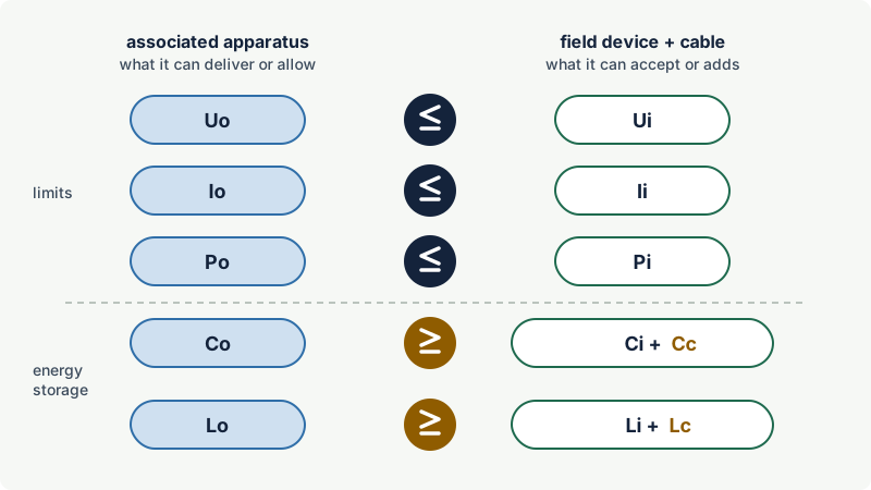
For a loop with one source of power, check in this order:
- Group. The associated apparatus and the field device must both suit the gas group (IIC parts can be used in IIB and IIA). Use the Co and Lo stated for the group of the location.
- Level of protection. The loop takes the lowest level of its parts. An
[Ex ia]isolator with anEx ibtransmitter gives an ib loop. - Voltage, current, power. Uo ≤ Ui, Io ≤ Ii, Po ≤ Pi. If only some of Ui, Ii and Pi are given, the safety of the device is fully defined by those, and the missing ones need not be compared.
- Capacitance. Ci (all field devices) + Cc (cable) ≤ Co.
- Inductance. Li (all field devices) + Lc (cable) ≤ Lo. Alternatively, if the field device inductance is negligible (less than 1 % of Lo), the cable is acceptable when its Lc/Rc does not exceed Lo/Ro, regardless of length.
- Temperature class and ambient. The temperature class comes from the field device (or the assessment of simple apparatus), not from the associated apparatus. Check the ambient range of each part.
- Earthing and insulation. The circuit must be floating or earthed at one point only; parts that do not pass a 500 V insulation test to earth count as earthed.
- Um. Equipment connected to the non-IS side must not be able to apply more than Um. Where Um is below 250 V, IEC 60079-14 restricts how the supply may be derived (for example from SELV or PELV systems or a safety isolating transformer).
A simple apparatus (switch, RTD, thermocouple) has no certified parameters. It is accepted on the basis of its definition, with any capacitance or inductance it contains added to the sums, and is normally classed T4 when the source cannot deliver more than 1.3 W at an ambient up to 40 °C.
Cable capacitance and inductance
The cable is usually the largest contributor of capacitance and inductance in the loop, and in IIC it often limits the permitted length.
Where the values come from
IEC 60079-25 accepts cable parameters from one of three sources:
- The most onerous values given by the cable manufacturer (for a screened pair, the capacitance including the screen connection is usually the relevant one).
- Measurement of a sample by the method in the standard.
- For two or three cores of conventionally constructed cable, with or without screen: 200 pF/m and either 1 µH/m or an Lc/Rc ratio equal to 1 µH divided by the loop resistance per metre. For currents up to 3 A, an L/R ratio of 30 µH/Ω may be used instead.
Why L/R often removes the inductance limit
The inductance of a cable grows with its length, but so does its resistance. The resistance limits the current that can flow into a fault at the far end, and with it the energy the inductance can store. When the field device has negligible inductance, comparing the cable's L/R with the source's Lo/Ro takes both effects into account. Typical instrument cables have an L/R well below the Lo/Ro of common sources, so the length is then limited by capacitance alone.
The 1 % rule for lumped L and C
The ignition curves assume a circuit with either inductance or capacitance. When a circuit contains both as lumped values (in the field devices, not distributed in a cable), the capacitor can reinforce the source feeding the inductor. IEC 60079-11 and IEC 60079-25 deal with this as follows:
- If either the total Li or the total Ci of the field devices (excluding the cable) is less than 1 % of Lo or Co respectively, the full Co and Lo can be used.
- If both are 1 % or more, Co and Lo are halved. The halved capacitance is limited to 600 nF for IIC and 1 µF for IIB, IIA and Group I.
In practice this rarely bites, because most transmitters have a small Li. Some certificates also state combined pairs of Co and Lo that may be used together; these take precedence over the simple rule.
Multi-core cables
Several IS circuits may share one multi-core cable if the cable meets the construction and dielectric test requirements of IEC 60079-25 (types A, B and C, depending on screening and protection). The fault analysis then has to consider connections between circuits in the same cable, and non-IS circuits must never share it.
Worked example: a IIC transmitter loop
A pressure transmitter in Zone 0 at a IIC process is connected to a galvanically isolated interface in the control room through 350 m of screened two-core cable. The values below are illustrative; real values come from the certificates and the cable data sheet.
| Item | Associated apparatus [Ex ia Ga] IIC | Transmitter Ex ia IIC T4 Ga | Cable (350 m) | Check |
|---|---|---|---|---|
| Voltage | Uo = 28 V | Ui = 30 V | - | 28 ≤ 30: pass |
| Current | Io = 93 mA | Ii = 100 mA | - | 93 ≤ 100: pass |
| Power | Po = 0.65 W | Pi = 0.75 W | - | 0.65 ≤ 0.75: pass |
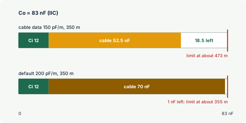
| Capacitance | Co = 83 nF | Ci = 12 nF | 150 pF/m × 350 m = 52.5 nF | 12 + 52.5 = 64.5 ≤ 83: pass |
| Inductance | Lo = 4.0 mH | Li = 20 µH | 0.6 µH/m × 350 m = 0.21 mH | 0.02 + 0.21 = 0.23 ≤ 4.0: pass |
| L/R (alternative) | Lo/Ro = 54 µH/Ω | - | Lc/Rc = 25 µH/Ω | 25 ≤ 54: pass |
| 1 % rule | - | Li/Lo = 0.5 %, Ci/Co = 14 % | - | Li below 1 %: no reduction |
Conclusions:
- The loop is ia, IIC, T4, suitable for Zone 0 at ambient temperatures within the range of both devices.
- The capacitance margin is 18.5 nF, so the cable could be extended to about 473 m before Co is reached. Inductance is not limiting.
- With the default values of 200 pF/m and 1 µH/m instead of the cable data, the same loop would use 82 nF of the 83 nF and would reach its limit at about 355 m. Real cable data is worth having.
Now suppose the transmitter is later replaced by a different model with Ui = 24 V. The comparison fails at the first line (28 V > 24 V) even though the loop would work electrically. The replacement is not acceptable on this interface, which is why every change of field device or associated apparatus needs the loop assessment repeated.
Notes on the example values:
- Io = 93 mA and Po = 0.65 W are what a 28 V source with a 300 Ω current-limiting resistor gives; 28/300 = 0.093 A and 28 × 0.093 / 4 = 0.65 W.
- Co = 83 nF is the IIC value tabulated in IEC 60079-11 for 28 V with a 1.5 safety factor, and 54 µH/Ω is the Lo/Ro that the standard's formula gives for 28 V and 300 Ω in IIC.
More than one source, and ic loops
The entity rules above assume one source of power. If two or more sources can feed the same circuit (two interfaces on one loop, or an active field device that also supplies energy), the voltages and currents may add, in series or in parallel, depending on the faults considered. IEC 60079-14 gives annexes for combining several sources with linear and non-linear characteristics; the combined values are then compared as above.
Where a source certified ia or ib is used in a loop that only needs level ic (Zone 2), its Co, Lo and Lo/Ro were derived with a 1.5 safety factor that ic does not require. IEC 60079-25 notes that the permitted values can be derived again with a factor of 1.0, and that multiplying them by two is an acceptable conservative shortcut. The loop is then ic and must be documented and labelled as such.
FISCO for fieldbus systems
A fieldbus segment can carry up to 32 devices on one cable, which makes a device-by-device entity calculation awkward and sensitive to every change. The fieldbus intrinsically safe concept (FISCO), now part of IEC 60079-11 (apparatus) and IEC 60079-25 (systems), replaces the calculation with fixed limits on every component. The values below are those of IEC 60079-11:2011 and IEC 60079-25:2010; the 2023 edition of IEC 60079-11 keeps the FISCO apparatus requirements in a normative annex, so check the current editions for any change:
| FISCO element | Requirement (ia and ib systems) |
|---|---|
| Power supply | Uo 14 to 17.5 V; Io not above 380 mA; Po not above 5.32 W; only one supply per segment |
| Field devices | Ui at least 17.5 V, Ii at least 380 mA, Pi at least 5.32 W; unprotected Ci not above 5 nF, Li not above 10 µH; up to 32 devices |
| Terminators | Up to two, at the ends of the trunk |
| Cable | Loop resistance 15 to 150 Ω/km, inductance 0.4 to 1 mH/km, capacitance 45 to 200 nF/km |
| Lengths | Each spur up to 60 m; trunk including all spurs up to 1 km in IIC and 5 km in IIB |
If every component is FISCO-certified and the cable meets these limits, the system is considered safe without calculating cable parameters, and the documentation can be reduced to a list of the equipment. For IIC the permissible supply current is well below 380 mA and depends on Uo and on the output characteristic of the supply, so IIC segments carry less power than IIB ones.
Documenting the loop
IEC 60079-25 requires a descriptive system document for every intrinsically safe system. It is also what an inspector will ask for. A practical record for each loop or loop type contains:
- the associated apparatus, field devices and simple apparatus, with certificate numbers and markings;
- the comparison table, as in the example above, including cable type, length and parameters;
- the resulting level of protection, group and temperature class;
- the earthing arrangement and the point where the circuit is earthed, if any;
- any specific conditions of use from the certificates ("X" conditions).
Common mistakes
- Comparing operating values instead of safety values. A 24 V supply does not make Uo = 24 V; use the certified Uo of the interface.
- Forgetting the cable. Ci + Cc and Li + Lc must be checked, especially in IIC and on long runs.
- Using IIB values in a IIC area. Co and Lo depend on the gas group; at 28 V the IIB value of Co is almost eight times the IIC value.
- Adding devices to a loop without redoing the sums. A second indicator or a solenoid on the same loop adds its Ci and Li and may add a second source.
- Treating a simple apparatus as zero. Its capacitance, inductance, temperature class and insulation to earth still need to be stated.
- Not recording the assessment. Without a descriptive system document, an inspector cannot confirm that the loop is intrinsically safe.
Frequently asked questions
What is the entity concept in intrinsic safety?
The entity concept is a way of checking that certified intrinsically safe apparatus and associated apparatus can be connected safely, by comparing parameters on their certificates. The source's Uo, Io and Po must not exceed the field device's Ui, Ii and Pi, and the field device plus cable must stay within the source's Co and Lo.
How do I calculate the maximum cable length for an IS loop?
Subtract the field device capacitance from Co and divide by the cable capacitance per metre; do the same for inductance with Lo, Li and the inductance per metre. The shorter result is the limit. If the field device inductance is negligible and the cable L/R is below the source's Lo/Ro, only the capacitance limit applies.
What cable capacitance should I use if I do not know it?
IEC 60079-25 allows 200 pF/m and 1 µH/m for two or three cores of conventional cable, with or without screen. These values are conservative; using the manufacturer's data or a measurement usually allows longer runs.
Is Po = Uo × Io / 4 always true?
Only for a linear source with a resistive current limit, where maximum power is delivered into a load equal to the source resistance. Interfaces with electronic or trapezoidal current limiting can deliver more, so always use the Po stated on the certificate.
What is the difference between the entity concept and FISCO?
The entity concept checks each connection by comparing parameters and adding cable values. FISCO is a predefined system for fieldbus segments: if the supply, devices, terminators and cable all meet the FISCO limits, the system is safe without calculation, which makes adding and replacing devices much simpler.
Do I need to redo the verification when replacing a transmitter?
Yes, unless the replacement has the same certificate and parameters. A different model can have a lower Ui or Pi, or a higher Ci, which changes the result even though it works electrically.
Related on excodex
- Intrinsic safety (Ex i): ia, ib and ic
- Zener barriers vs galvanic isolators
- Ex installation basics under IEC 60079-14
- Inspection of Ex installations under IEC 60079-17
- Earthing, bonding and equipotential bonding in hazardous areas
- Tools: Ex marking check, forum, standards spaces IEC 60079-25, IEC 60079-11 and IEC 60079-14
Standards and further reading
- IEC 60079-25, Explosive atmospheres: intrinsically safe electrical systems (third edition, 2020, with amendment 1 of 2025).
- IEC 60079-11, Explosive atmospheres: equipment protection by intrinsic safety "i" (seventh edition, 2023), including the FISCO apparatus requirements.
- IEC 60079-14, design, selection and installation of electrical installations (sixth edition, 2024), including annexes on circuits with more than one power source.
- IEC 61158-2, industrial communication networks: physical layer specification (the bus physical layer that FISCO is built on).
- IEC webstore, IEC 60079-25:2020 abstract: webstore.iec.ch
- IEC 60079-14:2024 preview with contents and table of significant changes: cdn.standards.iteh.ai
- IEC 60079-25:2010 (edition 2, superseded) text, incorporated by reference in US federal regulations, with the cable parameter options and the informative annex on lumped inductance and capacitance: law.resource.org; IEC webstore (current edition, IEC 60079-25:2020+AMD1:2025): webstore.iec.ch
This article is general technical information prepared by the excodex editorial team. It does not replace the applicable standards, the equipment certificates and instructions, national regulations or the assessment of a competent person.