Earthing, bonding and equipotential bonding in hazardous areas
Abstract
Protective earthing, equipotential bonding, intrinsic safety earth, static bonding, lightning protection and cathodic protection in hazardous areas: what each does, the usual criteria (6 mm², 1 Ω, 10 Ω, 1 MΩ) and where they conflict.
In a hazardous area, earthing and bonding exist mainly to stop sparks and hot spots, not only to protect people from electric shock. Protective earthing makes faults clear quickly; equipotential bonding keeps every exposed and extraneous metal part at the same potential so that no spark can jump between them; a dedicated intrinsic safety earth keeps zener barriers safe; static bonding drains charge from conductive items; and lightning and cathodic protection systems must be integrated so that their currents do not create new ignition sources. IEC 60079-14 requires equipotential bonding for every installation in a hazardous area.
This article separates the different jobs, gives the usual criteria with their sources, and explains the cases where more bonding is not the answer, such as insulating flanges on cathodically protected pipelines and ship-to-shore connections.
Key points
- IEC 60079-14 requires potential equalisation in hazardous areas: all exposed and extraneous conductive parts are connected to the equipotential bonding system, through designed connection points that are secured against loosening and corrosion.
- A TN supply system must be TN-S within the hazardous area: the neutral and the protective conductor are separate, and no combined PEN conductor is allowed there.
- Zener barriers need a dedicated earth connection; the values usually quoted from IEC 60079-14 are at least 4 mm² copper (or two separate conductors of at least 1.5 mm²) and less than 1 Ω to the main earthing point of a TN-S power system. Galvanic isolators do not need this intrinsic safety earth.
- For static electricity, IEC TS 60079-32-1 treats a metal item as adequately earthed with a resistance to earth of up to 1 MΩ, while a resistance above about 10 Ω across a direct metal-to-metal bond suggests a poor or corroded connection.
- Cathodically protected pipelines are deliberately isolated from plant earth by insulating joints; bridging them carelessly, or bonding a ship to the shore with a cable, can itself produce incendive arcs.
- Lightning protection to the IEC 62305 series must be bonded into the same earthing system, and intrinsically safe circuits exposed to lightning may need surge protection.
Four jobs with four different criteria
Most confusion about earthing in hazardous areas comes from mixing up systems that share copper and earth electrodes but have different purposes and very different acceptance values.
| System | What it prevents | Typical criterion | Main reference |
|---|---|---|---|
| Protective earthing | Dangerous touch voltage and long-lasting fault currents | Fault loop low enough for the protective device to disconnect in time | IEC 60364 series, IEC 60079-14 |
| Equipotential bonding | Sparks between metal parts at different potentials | Main bonding conductor at least 6 mm² Cu, additional connections at least 4 mm² Cu | IEC 60079-14, IEC 60364-5-54 |
| Intrinsic safety earth | Fault voltages reaching an intrinsically safe circuit through a zener barrier | Usually quoted: at least 4 mm² Cu (or 2 x 1.5 mm²), below 1 Ω to the power system earth (TN-S) | IEC 60079-14 |
| Static earthing and bonding | Accumulation of electrostatic charge on conductive items | Up to 1 MΩ to earth for metal items; metal bonds normally below 10 Ω | IEC TS 60079-32-1 |
The numbers are not interchangeable. A 1 MΩ path drains static charge perfectly but would never clear an electrical fault, and a protective conductor that meets the fault criteria says nothing about whether a drum standing on a plastic pallet is earthed.
Protective earthing and the supply system
The type of system earthing affects the risk of sparking in normal operation, not just under fault.
TN systems must be of type TN-S in the hazardous area. In a TN-C arrangement the combined neutral and protective conductor (PEN) carries the load current, so part of that current can flow through pipework, structures and cable armour that are bonded to it. Every bolted joint and loose contact in that path becomes a potential spark source. Where a TN-C-S supply is used, the transition to TN-S is made outside the hazardous area, and the protective conductor is connected to the equipotential bonding system at the transition point.
TT systems rely on residual current devices, because the earth fault loop impedance is usually too high to operate overcurrent devices quickly.
IT systems allow operation to continue after a first earth fault, which is attractive for critical drives, but only if the first fault is detected. IEC 60079-14 calls for an insulation monitoring device for this purpose, and the second fault must still be cleared.
Electric trace heating is a special case. IEC 60079-14 requires earth fault protection in addition to overcurrent protection: in TT and TN systems a residual current device with a rated residual operating current of not more than 100 mA, with 30 mA preferred, and in IT systems an insulation monitoring device to IEC 61557-8.
Equipotential bonding
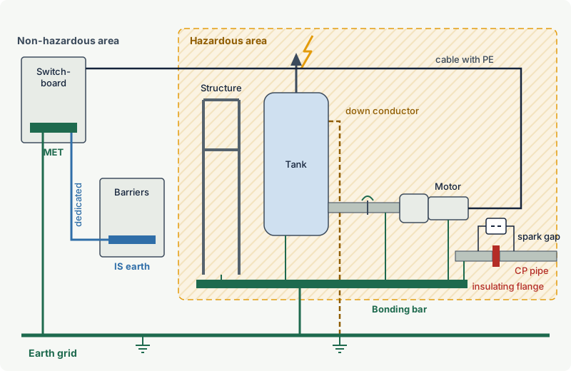
Equipotential bonding, also called potential equalisation, connects every conductive part that could reach a different potential to a common bonding system, so that no voltage can build up between two parts a person or a tool might bridge.
What must be bonded. Exposed conductive parts (enclosures, motor frames, luminaire bodies, cable trays carrying power cables) and extraneous conductive parts (structural steel, pipework, vessels, handrails, metal ducting). IEC 60079-14 has long accepted that a part firmly fixed to, and in metallic contact with, a structure or pipe that is itself bonded does not need its own conductor. Contact through paint, gaskets or loose fixings does not count.
Conductor sizes. IEC 60079-14:2024, in line with IEC 60364-5-54, calls for a protective equipotential bonding conductor of at least 6 mm² copper and additional bonding connections of at least 4 mm² copper. Mechanical strength often decides the size instead: the 2024 edition notes that 16 or 25 mm² may be needed, and exposed outdoor bonds on skids and structures are commonly of that size.
Connections. Bonds must be made at designed connection points, such as the external earth terminal of an Ex enclosure or a welded boss, never by relying on fortuitous contact. Connections must be secured against self-loosening and protected against corrosion. The 2024 edition of IEC 60079-14 asks for an arrangement in which removing a single connection does not break the bonding of other items, and recommends a bonding rail with one conductor per item rather than conductors looped from one item to the next.
Cable armour and glands. Armour and braid are terminated in the cable gland and bonded, so they cannot float at a different potential. On non-metallic enclosures there is no metal body to carry the bond, so glands with an earth tag or an internal bonding plate are used to connect the armour to the bonding system.
The intrinsic safety earth
A zener (shunt diode) barrier protects an intrinsically safe circuit by diverting fault current to earth through its diodes until its fuse blows. If the barrier earth is missing or has high resistance, a fault on the safe-area side can drive dangerous voltage into the hazardous-area circuit. The earth connection is therefore part of the protection concept, not a functional extra.
The requirements usually quoted from IEC 60079-14 are:
- a dedicated, insulated copper conductor of at least 4 mm², or two separate conductors each of at least 1.5 mm² so that one can be disconnected for testing while the other remains;
- a resistance of less than 1 Ω between the barrier earth bar and the main earthing point of the power system (in TN-S systems), with the connection kept as short and direct as practicable;
- connection to the equipotential bonding system in a way that cannot be broken by routine work on other equipment.
Galvanic isolators separate the hazardous-area circuit from the supply with transformers or optocouplers, so they do not need an intrinsic safety earth. Cable screens and any static drain path still need earthing.
Screens and armour. The screen of an intrinsically safe cable is normally earthed at one point only, usually at the barrier end, and kept insulated from earth in the hazardous area so that circulating earth currents cannot flow along it. Armour and metallic sheaths, which will contact earth in the field anyway, are bonded to the plant bonding system and not to the barrier earth.
Static earthing and bonding
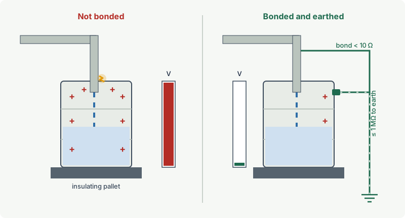
Static electricity behaves differently from power-system faults. Charging currents in industrial processes are small, rarely more than about a microampere and often far less, so a resistance to earth that would be useless for fault protection is enough to keep voltage low. What matters is that no conductive item is left isolated, because an isolated item can store charge and release it in a single spark.
IEC TS 60079-32-1 (electrostatic hazards guidance, 2013 with Amendment 1 of 2017) gives the usual criteria:
- metal items are adequately earthed for static purposes with a resistance to earth of not more than 1 MΩ, and up to 100 MΩ is acceptable for small items with capacitance below 100 pF;
- where earthing relies on a direct metal-to-metal bond, the resistance should be below 10 Ω, because a higher value usually means corrosion, paint or a poor contact that may get worse;
- people working where vapours have low ignition energies should have a resistance to earth of less than 100 MΩ, usually achieved with dissipative footwear on a suitable floor.
Movable items are the main problem: drums, intermediate bulk containers, road tankers, hoses, funnels, sampling cans and portable equipment. They are bonded before a transfer starts and disconnected only after it has finished and the charge has relaxed. Clamps must bite through paint and rust, and for road tankers many terminals use earth verification systems that check the connection and interlock the loading pump. Bolted metal pipe flanges normally provide adequate static continuity; bonding jumpers are needed where measurements show otherwise, for example across non-conductive gaskets, lined or plastic sections, or painted flange faces.
Lightning protection
A lightning strike to a structure, tank or pipe rack injects currents of tens of kiloamperes into the earthing system. If the lightning protection system and the plant bonding system are not connected, the potential difference between them can flash over at any point where they come close.
- Design the lightning protection to the IEC 62305 series, starting with a risk assessment. IEC 62305-3 (current edition 2024) covers protection measures for structures and, in its earlier edition, a normative annex for structures with a risk of explosion.
- Bond down conductors and earth electrodes into the common earth grid, and bond incoming services (pipes, cable armour, rails) where they enter the protected area.
- Keep air terminals, down conductors and the points where lightning current flows away from vents and other sources of release, as far as practicable.
- Protect sensitive circuits against surges. For intrinsically safe circuits, surge protective devices must be compatible with the intrinsic safety assessment (their capacitance and inductance count in the loop, and IEC 60079-25 asks for a documented analysis of the effect of the extra earth connections), and IEC 60079-14:2024 gives informative guidance on surge protection of intrinsically safe circuits in a new annex. Where an intrinsically safe circuit runs into Zone 0 from a structure exposed to lightning, the surge protective device is installed outside Zone 0, close to its boundary.
Cathodic protection and stray currents: when isolation beats bonding
Buried and immersed pipelines and tanks are often protected against corrosion by cathodic protection (CP), either with sacrificial anodes or with an impressed current from a rectifier. The protected structure is held at a negative potential relative to earth and is deliberately isolated from the plant earthing system by insulating flanges or joints. Otherwise the CP current would flow into the whole plant earth and protection would be lost.
This creates a real ignition risk. The potential difference across an insulating joint is small, but the current available can be large. If a tool, a ladder, a temporary bonding cable or a person bridges the joint, or a lightning surge flashes over it, the resulting arc can ignite a flammable atmosphere. IEC 60079-14 has a dedicated subclause on cathodically protected metallic parts. As it is usually summarised from the published editions, it treats them as live extraneous conductive parts that remain potentially dangerous despite their low negative potential, allows cathodic protection in Zone 0 only with a system specially designed for that application, and recommends locating the insulating elements outside the hazardous area where possible. Check the wording of the current edition before quoting it in a specification.
Practical measures:
- Where an insulating joint must be inside a hazardous area, bridge it with an Ex-certified isolating spark gap. The gap blocks the CP current in normal operation but breaks down in a controlled way inside its own Ex enclosure during a surge, so the flashover does not happen in the open air across the flange.
- Locate CP rectifiers outside hazardous areas, or use equipment certified for the location; US Unified Facilities Criteria guidance makes the same point.
- Before cutting a cathodically protected pipeline, or opening a flange on it, install a temporary bond across the cut point and consider switching off the impressed current, because the voltage gradient can cause an arc when the pipe is separated.
- At marine terminals, do not bond ship and shore with a cable. Industry guidance (ISGOTT, and a SIGTTO justification paper reviewing the research) explains that the ship and the jetty form a low-resistance galvanic cell with large available current, which a bonding cable cannot equalise but can spark when connected or disconnected. The accepted solution is an insulating flange or one length of electrically discontinuous hose in each transfer line, while static is handled separately on each side.
Worked example: verifying earthing and bonding on a pump skid
A new pump skid in Zone 1 handles toluene (gas group IIA, flash point 4 °C in the excodex library). The skid has an Ex db motor, an Ex d junction box, two intrinsically safe transmitters fed through zener barriers in the control room, and a flexible hose connection for a drum filling point. The commissioning team records these measurements (illustrative values):
| Measurement | Result | Criterion | Verdict |
|---|---|---|---|
| Skid bonding boss to plant bonding bar | 0.04 Ω | Low resistance, conductor at least 4 mm² (16 mm² fitted) | Acceptable |
| Motor frame to skid bonding boss | 0.02 Ω | Continuity of bond through designed terminal | Acceptable |
| Junction box external earth terminal to skid | 0.03 Ω | Continuity | Acceptable |
| Barrier earth bar to main earthing terminal | 0.35 Ω | Below 1 Ω, dedicated 4 mm² conductor | Acceptable |
| Drum filling hose metal end fitting to earth | 40 MΩ | Not more than 1 MΩ for a metal item | Not acceptable |
| Pipe flange across PTFE gasket, bolts painted | 120 Ω | Below 10 Ω for a metal bond | Investigate and fit jumper |
The hose turns out to have a non-conductive inner layer and an end fitting that is not connected to its wire helix. It is replaced by a hose with a specified, continuous conductive path, and the drum filling point gets a bonding clamp. The painted flange is fitted with a bonding jumper on cleaned contact faces. All results go into the verification dossier, together with the instrument details, so that periodic inspection under IEC 60079-17 can compare later values.
Common mistakes
- Looping bonding conductors from item to item. Removing one item for maintenance then disconnects all those downstream. Use a bonding rail with one conductor per item.
- Relying on paint-covered bolts or mounting brackets as the bond. Use the designed earth terminal and make the connection on clean metal, protected against corrosion afterwards.
- Sharing the IS earth with other functions or routing it through a series of panels. It needs its own dedicated, short, insulated path to the power system earth, verified below 1 Ω.
- Applying fault-current thinking to static. A 1 MΩ path is enough for static, but a drum on a plastic pallet with no path at all is not earthed even if the building's earthing is perfect.
- Bridging an insulating flange "to be safe". It defeats the cathodic protection and moves the arc to wherever the bridge is broken. Use an Ex-certified spark gap where a bridge is needed, and a temporary bond before cutting a pipeline.
- Earthing IS cable screens at both ends. Circulating earth currents can then flow along the screen; earth it at one point unless the design specifically requires otherwise.
Frequently asked questions
What is the difference between earthing and bonding in a hazardous area?
Earthing connects equipment to the general mass of earth through the protective conductor so that faults are cleared and touch voltages stay safe. Bonding connects conductive parts to each other so they stay at the same potential and no spark can occur between them. In hazardous areas both are required, and IEC 60079-14 specifically calls for equipotential bonding of all exposed and extraneous conductive parts.
What size should an equipotential bonding conductor be in a hazardous area?
IEC 60079-14:2024, in line with IEC 60364-5-54, gives at least 6 mm² copper for the protective equipotential bonding conductor and at least 4 mm² copper for additional bonding connections. Larger sizes such as 16 or 25 mm² are often chosen for mechanical strength in exposed outdoor locations.
What resistance is required for an intrinsic safety earth?
For zener barriers, the usually quoted requirement of IEC 60079-14 is less than 1 Ω between the barrier earth bar and the main earthing point of the power system (for TN-S systems), using at least one 4 mm² copper conductor or two separate conductors of at least 1.5 mm². Galvanic isolators do not need an intrinsic safety earth.
What resistance to earth is acceptable for static bonding?
IEC TS 60079-32-1 considers a metal item adequately earthed for static purposes with a resistance to earth of up to 1 MΩ, because static charging currents are tiny. For a direct metal-to-metal bond, a value above about 10 Ω indicates a poor connection that should be investigated.
Should a ship be bonded to the shore when loading flammable cargo?
No. International tanker and terminal guidance replaced ship-to-shore bonding cables with insulating flanges or electrically discontinuous hose lengths, because large galvanic and stray currents between ship and jetty can cause arcs when a cable is connected or disconnected. Static on each side is handled by that side's own earthing.
Can a PEN conductor be used in a hazardous area?
No. If a TN system is used, it must be TN-S within the hazardous area, with separate neutral and protective conductors. A combined PEN conductor would let load current flow through bonded metalwork, where any poor joint could spark.
Related on excodex
- Static electricity as an ignition source: charging, discharges and bonding
- Ex installation basics under IEC 60079-14
- Zener barriers vs galvanic isolators: choosing intrinsic safety interfaces
- Cable glands for hazardous areas: barrier glands, compound glands and selection
- Hot work permits in hazardous areas
- Standards spaces: IEC 60079-14, IEC 60079-11, IEC 60079-17, and the forum
Standards and further reading
- IEC 60079-14:2024, electrical installations design, selection and installation of equipment, including initial inspection (edition 6.0): equipotential bonding, system earthing, intrinsic safety earthing, cathodically protected parts
- IEC 60364-5-54, earthing arrangements and protective conductors; IEC 61557-8, insulation monitoring devices for IT systems
- IEC TS 60079-32-1:2013 with Amendment 1:2017, electrostatic hazards, guidance: IEC webstore
- IEC 62305 series, protection against lightning; IEC 62305-3 for structures (edition 2024 replaced the 2010 edition): IEC webstore, 2010 edition page
- IEC 60079-25, intrinsically safe electrical systems, including the assessment of surge protection in intrinsically safe loops
- P. Thurnherr (convenor of IEC maintenance team MT 60079-14), "Electrical installations design, selection and installation of equipment, including initial inspection", presentation summarising IEC 60079-14:2024 at the 2024 IECEx International Hydrogen Conference, Singapore: presentation PDF
- IEC 60079-14:2024 preview pages with the table of significant changes (equipotential bonding connections, TN earthing, cathodically protected metallic parts): sample pages
- J. Smallwood, "IEC 60079-32-1: the new standard on avoidance of electrostatic hazards", IChemE Hazards 25 (2015): paper PDF
- SIGTTO, "A justification into the use of insulation flanges and electrically discontinuous hoses at the ship/shore and ship/ship interface": paper PDF
This article is general technical information prepared by the excodex editorial team. It does not replace the applicable standards, the equipment certificates and instructions, national regulations or the assessment of a competent person.