Zener barriers vs galvanic isolators: choosing intrinsic safety interfaces
Abstract
Zener barriers divert fault energy to a high-integrity earth; galvanic isolators block it with transformer isolation and need no IS earth. How each works, barrier earthing rules, pros and cons, a voltage budget example and when to choose which.
Zener barriers and galvanic isolators are both associated apparatus: they sit between the control system and an intrinsically safe field circuit and limit the energy that can reach the hazardous area. A zener barrier is a passive network of a fuse, a current-limiting resistor and shunt zener diodes; in a fault it diverts the excess current to earth, so it only works with a high-integrity intrinsic safety (IS) earth and a field circuit that is otherwise isolated from earth. A galvanic isolator separates the hazardous-area circuit from the supply and the control system with transformers or optocouplers, so it needs no IS earth and tolerates earthed field devices, at a higher cost and with its own power supply.
This article explains how each interface works, the earthing requirements of zener barriers, the advantages and limitations of both, a voltage budget example, and a practical way to choose.
Key points
- Both interfaces are certified associated apparatus, marked for example
[Ex ia Ga] IIC, with output parameters (Uo, Io, Po, Co, Lo) that are checked against the field device and cable in the same way. - A zener barrier limits voltage with shunt zener diodes and current with a resistor; a fuse protects the diodes. Fault current from the non-hazardous side flows to earth, so the barrier earth is part of the protection.
- IEC 60079-14 requires the barrier earth to be connected to the equipotential bonding system by the shortest practicable route (or, in TN-S systems, to a high-integrity point with less than 1 Ω to the main power system earth), using one copper conductor of at least 4 mm² or two separate conductors of at least 1.5 mm² each.
- With a zener barrier the IS circuit is already earthed at the barrier, so field devices and cable screens must be insulated from earth in the field (able to withstand a 500 V test).
- A galvanic isolator provides isolation between the hazardous-area circuit, the safe-area circuit and the supply; no IS earth is needed, and the field circuit may be earthed at one point.
- Isolators cost more, need power and dissipate heat, but reject earth potential differences and noise; barriers are simple, compact and cheap, but depend on the earth and introduce a series voltage drop.
How a zener barrier works
A shunt diode safety barrier, usually called a zener barrier, contains three kinds of component in a sealed (typically encapsulated) module:
- A fuse in series with the input. It does not protect the hazardous area directly; it limits the fault current the zener diodes have to carry, and for how long, so that they can be rated for it.
- Shunt zener diodes between the signal line and the common (earthed) line. Below their breakdown voltage they draw almost no current. When the input voltage rises above it, they conduct and hold the output at the zener voltage. Several diodes in parallel give redundancy, so that one failed diode does not remove the voltage limit; IEC 60079-11 requires at least two parallel diode paths for an infallible shunt assembly.
- A current-limiting resistor between the diodes and the hazardous-area terminal. It limits the current into a short circuit in the field to Io = Uo / R and is built as an infallible component.
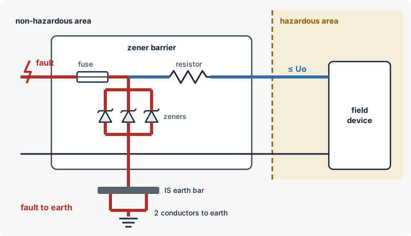
What happens in a fault
Suppose a wiring error or a failure in the control system puts mains voltage on the barrier input. The zener diodes conduct and clamp the output at Uo, and the fault current flows through the diodes, into the common line and away through the barrier earth. The fuse then blows. At no point can the hazardous-area circuit see more than Uo, or deliver more than Io into a short circuit.
The maximum voltage the input may be exposed to is the barrier's Um, commonly 250 V. Everything connected on the non-hazardous side must be unable to apply more than Um, even in a fault.
Polarity and variants
Barriers are made for positive or negative signals, for a.c. signals (with back-to-back diodes), and with "diode return" channels that let a current return from the field without adding energy. Each channel only works for the signal type and polarity it was designed for, so the barrier type has to match the loop. The internal fuse is usually not replaceable; a barrier with a blown fuse is normally replaced, and some designs include an additional replaceable supply-side fuse.
Earthing requirements for zener barriers
Without an earth, a barrier controls the voltage between its two output terminals but not the voltage between those terminals and the plant earth in the hazardous area. A fault on the non-hazardous side could then lift the whole IS circuit to a dangerous potential relative to earthed metalwork in the field. That is why the barrier earth is a safety connection, not a functional one.
The connection
The requirements of IEC 60079-14, in summary (as worded in the 2013 edition; the 2024 edition restructured the standard, so check the current clause):
- Connect the barrier earth terminals (usually a common busbar) to the equipotential bonding system by the shortest practicable route. In TN-S systems, an alternative is a high-integrity earth point with an impedance of less than 1 Ω to the main power system earth point.
- Use either one copper conductor of at least 4 mm² or two separate conductors of at least 1.5 mm² each, each able to carry the maximum continuous fault current.
- Two separate conductors are often preferred because one can be disconnected to test the connection while the other keeps the barriers earthed.
- Protect and identify the conductors and terminations so they are not removed by mistake.
The rest of the circuit must be floating
IEC 60079-25 and IEC 60079-14 require, in general, that an intrinsically safe circuit is either fully floating or earthed at one point only, with the rest of the circuit insulated to withstand a 500 V test. A zener barrier already earths the circuit at the barrier, so:
- field devices must be insulated from earth (a thermocouple welded to a vessel, an earthed sensor or an analyser with an earthed signal input defeats this);
- cable screens are normally earthed at the barrier end and kept insulated from earth in the hazardous area;
- cable armour and metallic sheaths are bonded to the plant earth through their glands like any other armour; they are not part of the IS circuit and must not be joined to its conductors or its screen in the field.
A second earth connection creates a loop through which differences in earth potential across the plant can drive current through the IS wiring. IEC 60079-25 notes that where significant potential differences (more than 10 V) between the structure and the circuit can occur, galvanic isolation is the preferred technique.
Inspection
IEC 60079-17 lists the earthing or insulation of IS circuits among the items to inspect. For barrier systems this means checking that the earth conductors are present, tight and uncorroded, and measuring the earth connection, typically one conductor at a time. For more on bonding see earthing and bonding in hazardous areas.
How a galvanic isolator works
A galvanic isolator (also called an isolated barrier or isolating interface) has no conductive path between the hazardous-area circuit and the rest of the system. A typical three-port isolator separates three circuits:
- the supply (often 24 V d.c.), which feeds the isolator through an isolating DC/DC converter;
- the safe-area signal circuit, connected to the control system;
- the hazardous-area circuit, connected to the field device.
Power and signals cross the isolation through transformers, and some signals through optocouplers. The isolation is built to the separation and dielectric strength requirements of IEC 60079-11; between intrinsically safe and non-intrinsically safe circuits the test voltage is twice the sum of the circuit voltages plus 1 000 V, with a minimum of 1 500 V r.m.s.
The hazardous-area side still has an energy-limiting stage, so the isolator has output parameters like a barrier. The difference is that a fault on the supply or the control system side is stopped by the isolation instead of being dumped into earth. No IS earth is required for intrinsic safety, and the field circuit can be earthed at one point if the instrument needs it. Since the 2023 edition of IEC 60079-11, the term "diode safety barrier" explicitly no longer covers devices that provide galvanic isolation.
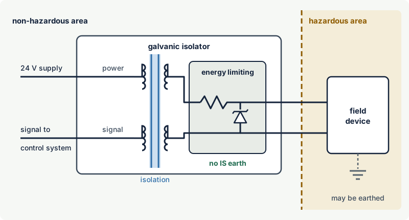
Some isolators are loop-powered, drawing their energy from the signal loop itself, and others combine supply and signal on the safe side (two-port). Because the electronics are active, isolators can also convert and condition signals, pass digital communication superimposed on 4-20 mA signals, detect open and short circuits in the field wiring, drive relay outputs, and be certified for use in safety instrumented functions.
Zener barriers vs galvanic isolators: pros and cons
| Aspect | Zener barrier | Galvanic isolator |
|---|---|---|
| Protection principle | Diverts fault energy to earth | Blocks fault energy by isolation |
| IS earth | Required: high-integrity, documented and inspected | Not required for intrinsic safety |
| Field device and screen earthing | Field circuit must be insulated from earth | Field circuit may be earthed at one point |
| Earth potential differences and noise | Earth loops possible; common-mode noise reaches the signal | Breaks earth loops; good common-mode rejection |
| Supply | None of its own; passes the loop supply through | Needs a supply; dissipates heat in the cabinet |
| Signal | Direct analogue path; series resistance causes a voltage drop; leakage near the working voltage | Signal is converted and repeated; small conversion tolerance |
| Functions | Passes the signal only | Conditioning, line fault detection, relay outputs, safety-rated versions |
| Matching | Type and polarity must match the loop | Dedicated to a signal type, less sensitive to wiring polarity |
| Cost and size | Low cost, very compact, simple | Higher cost, larger, more complex |
| After a supply-side fault | Fuse may blow; barrier is replaced | Fault is contained by the isolation |
Both types are available as [Ex ia Ga], so either can supply circuits into Zone 0. The choice is about the installation, not about the level of protection.
Worked example: voltage budget of a 4-20 mA loop
A two-wire transmitter needs at least 12 V at its terminals. It is supplied from a 24 V power supply through a barrier and a 250 Ω input resistor in the control system. The barrier data sheet (illustrative values) gives an end-to-end resistance of 340 Ω and a maximum working voltage of 25 V.
| Current | Drop in barrier (340 Ω) | Drop in input resistor (250 Ω) | Voltage at transmitter | Result |
|---|---|---|---|---|
| 4 mA | 1.4 V | 1.0 V | 21.6 V | Fine |
| 20 mA | 6.8 V | 5.0 V | 12.2 V | Just enough |
| 22 mA (fault signalling) | 7.5 V | 5.5 V | 11.0 V | Too low: transmitter may drop out |
The supply cannot simply be raised to compensate, because above the barrier's working voltage the zener leakage current rises, which first distorts the measurement and eventually blows the fuse. The options are a lower input resistance, a barrier with lower end-to-end resistance (if its Io and the field device's Ii still match), or a galvanic isolator, which supplies the transmitter from its own isolated converter and is not limited in the same way.
A second common case: a thermocouple whose hot junction is welded to the process pipe is earthed in the field. On a zener barrier this creates a second earth point; on a galvanic isolator it is acceptable as the single earth point of the isolated circuit.
How to choose
Choose a galvanic isolator when:
- there is no reliable high-integrity earth, or it cannot be installed and maintained to the required standard;
- field devices or sensors are earthed, or cannot be guaranteed to withstand 500 V to earth;
- the plant is large or has significant earth potential differences, lightning exposure or electrical noise;
- the loop needs signal conditioning, line fault detection, relay outputs or a safety-rated interface;
- the supply voltage margin is tight, as in the example above.
A zener barrier remains a reasonable choice when:
- a good equipotential bonding system already exists and barrier earthing is part of the site's inspection routine;
- the field devices are floating simple apparatus, such as switches, RTDs or insulated thermocouples;
- cost, panel space and heat dissipation matter, or an existing barrier installation is being extended consistently;
- a direct, unconverted analogue path is wanted.
Whichever interface is used, the loop still has to be verified with the entity parameters, as explained in intrinsic safety loop verification.
Common mistakes
- Missing or loose barrier earth. Without it a zener barrier does not provide intrinsic safety. Check that both conductors are present and tight, and include them in inspections.
- Earthing the field side of a barrier circuit. An earthed sensor, a screen earthed in the field as well as at the barrier, or a circuit conductor touching earthed armour creates a second earth point. Use an isolator or insulate the field side.
- Running the supply above the barrier's working voltage. Leakage through the zener diodes distorts the signal and eventually blows the fuse.
- Using the wrong barrier polarity or type. A positive barrier on a negative loop, or a single-channel barrier on a floating two-wire circuit, does not give the intended protection or signal.
- Treating the isolator output as ordinary wiring. The hazardous-area side of an isolator is an intrinsically safe circuit: separation, identification and cable parameter rules still apply.
- Swapping interfaces without re-checking parameters. A replacement isolator or barrier with a higher Uo or Io may no longer match the field device.
Frequently asked questions
What is the difference between a zener barrier and a galvanic isolator?
A zener barrier limits energy with zener diodes and a resistor and sends fault current to earth, so it needs a high-integrity IS earth and a field circuit that is otherwise isolated from earth. A galvanic isolator transfers power and signals across transformer or optocoupler isolation, so faults cannot pass and no IS earth is needed.
Does a zener barrier need an earth?
Yes. The barrier earth is part of the type of protection: it carries the fault current when the zener diodes clamp an overvoltage. IEC 60079-14 requires a connection to the equipotential bonding system by the shortest practicable route, with one copper conductor of at least 4 mm² or two of at least 1.5 mm² each.
Can I use a zener barrier with a grounded thermocouple?
Not directly. A grounded (earthed) thermocouple puts a second earth on a circuit that the barrier already earths, which can drive circulating current through the IS wiring. Use a galvanic isolator, or an insulated thermocouple that withstands the 500 V test to earth.
Are galvanic isolators safer than zener barriers?
Both provide the same level of protection when correctly installed; both can be certified [Ex ia Ga]. Isolators are more forgiving of installation conditions because they do not depend on an earth connection and tolerate earthed field devices, which reduces the chance of an installation error defeating the protection.
Why do zener barriers cause measurement problems?
The series resistance of the barrier drops voltage at higher loop currents, which can starve two-wire transmitters, and zener leakage near the working voltage adds an error current. Earth loops through the barrier earth can also inject noise. Galvanic isolators avoid these effects.
Related on excodex
- Intrinsic safety (Ex i): ia, ib and ic
- Intrinsic safety loop verification
- Earthing, bonding and equipotential bonding in hazardous areas
- Ex installation basics under IEC 60079-14
- Common Ex inspection findings and how to fix them
- Tools: Ex marking check, forum, standards spaces IEC 60079-11, IEC 60079-14 and IEC 60079-25
Standards and further reading
- IEC 60079-11, Explosive atmospheres: equipment protection by intrinsic safety "i" (seventh edition, 2023), including the requirements for shunt diode safety assemblies and galvanic separation.
- IEC 60079-14, design, selection and installation of electrical installations (sixth edition, 2024), including the earthing of intrinsically safe circuits.
- IEC 60079-25, intrinsically safe electrical systems (third edition, 2020, with amendment 1 of 2025), including the single-point earthing rule.
- IEC 60079-17, inspection and maintenance of electrical installations (sixth edition, 2023).
- HazardEx, summary of the barrier earthing rules of IEC 60079-14: hazardex.com
- IEC 60079-11:2011 (edition 6, superseded) text, incorporated by reference in US federal regulations, with the requirements for diode safety barriers, shunt safety assemblies and galvanic separation: law.resource.org; IEC webstore (current edition, IEC 60079-11:2023): webstore.iec.ch
- IEC 60079-25:2010 (edition 2, superseded) text, with the earthing clause (floating or bonded at one point; galvanic isolation preferred where potential differences above 10 V can occur): law.resource.org; IEC webstore (current edition, IEC 60079-25:2020+AMD1:2025): webstore.iec.ch
- IEC 60079-11:2023 preview with the table of changes from edition 6: cdn.standards.iteh.ai
This article is general technical information prepared by the excodex editorial team. It does not replace the applicable standards, the equipment certificates and instructions, national regulations or the assessment of a competent person.