Ex installation basics under IEC 60079-14
Abstract
IEC 60079-14 sets the rules for designing, selecting, installing and initially inspecting electrical installations in explosive atmospheres. Scope, documentation, selection, wiring, cable entries, earthing, intrinsic safety and the verification dossier.
IEC 60079-14 is the international standard for electrical installations in explosive atmospheres. It tells the designer and the installer how to choose Ex equipment for a classified area, how to wire, enter, earth and protect it, and how to carry out the initial inspection before the plant is energised. The current edition is the sixth (IEC 60079-14:2024), adopted in Europe as EN IEC 60079-14:2024; it replaced the 2013 edition. Everything the installation relies on is recorded in a set of documents called the verification dossier.
This article walks through the standard in the order a project uses it: scope, documentation, equipment selection, design of the supply, wiring systems, cable entries, earthing and bonding, intrinsically safe circuits, and the initial inspection that closes the dossier.
Key points
- IEC 60079-14 covers the design, selection, installation and initial inspection of electrical installations in explosive gas and dust atmospheres; it adds to, and does not replace, the normal wiring rules for non-hazardous areas.
- The sixth edition (August 2024) restructured the standard into documentation, design, selection, installation and initial inspection; EN IEC 60079-14:2024 superseded EN 60079-14:2014, with conflicting national standards to be withdrawn by 4 October 2027.
- Equipment is selected by matching its marking to the site: EPL to the zone, equipment group to the gas or dust group, temperature class or maximum surface temperature to the ignition temperature, and the rated ambient range to the real ambient.
- Inside a hazardous area a TN system must be TN-S: the neutral and the protective conductor are not combined in one PEN conductor.
- Cable entries must keep the type of protection of the enclosure; for flameproof enclosures the 2024 edition introduced a flowchart, based on gas group, cable length and enclosure volume, that decides when a barrier-type entry is required.
- Before an installation is put into service it receives an initial inspection at detailed grade, and the records go into the verification dossier, the set of documents that shows the installation complies.
What IEC 60079-14 covers
The standard applies wherever an electrical installation sits in, or is associated with, an area classified because of flammable gas, vapour or combustible dust. It covers fixed, transportable, portable and personal equipment, and both permanent and temporary installations. Its requirements are additional to the general installation rules (IEC 60364 or the national wiring code): an Ex installation must first be a good ordinary installation.
The scope also lists what it does not cover: mines susceptible to firedamp, inherently explosive situations such as the manufacture and processing of explosives (and dusts of explosives or pyrophoric substances), rooms used for medical purposes, installations where the hazard comes from flammable mist, and toxic hazards. Non-electrical Ex equipment is outside its scope unless it forms part of an assembly under IEC TS 60079-46.
What changed in 2024
The sixth edition was published in August 2024. Its title changed from "design, selection and erection" to "design, selection and installation of equipment, including initial inspection", and the text is now organised as documentation, design, selection, installation and initial inspection. A table at the front of the standard lists the significant changes. Notable additions include a selection flowchart for flameproof cable entries with a new normative cable test, clarified rules for TN earthing and cathodically protected parts, cables under thermal insulation, pressurised rooms and analyser houses, simple apparatus, and informative initial inspection tables aligned with IEC 60079-17.
Many sites, contracts and national codes still refer to the 2013 edition (EN 60079-14:2014). Check which edition your contract or national law calls up.
Where IEC 60079-14 sits among the other parts
| Life-cycle step | Main standard |
|---|---|
| Area classification (gas, dust) | IEC 60079-10-1, IEC 60079-10-2 |
| Equipment construction and certification | IEC 60079-0 and the type of protection parts (-1, -2, -7, -11, -15, -18, -31 and others) |
| Design, selection, installation, initial inspection | IEC 60079-14 |
| Inspection and maintenance in service | IEC 60079-17 |
| Repair, overhaul and reclamation | IEC 60079-19 |
| Competence of persons | IECEx CoPC scheme, national schemes |
Documentation comes first
IEC 60079-14 puts documentation before design, because nobody can select or install equipment correctly without knowing the area, the certification and the intended connection. The required information falls into four blocks:
- Site information: the area classification documents and drawings, the gas, vapour or dust involved with its group and temperature class or ignition temperature, material characteristics where relevant, external influences and the ambient temperature range.
- Equipment information: the certificates, the manufacturer's instructions for selection, installation and initial inspection, the specific conditions of use for any certificate with the suffix "X", and the descriptive system document for intrinsically safe systems.
- Installation information: the information needed for correct installation, evidence that the equipment suits its location, wiring system drawings, records of how cable entries were selected, circuit identification schedules and the initial inspection records.
- Personnel information: evidence that the people who designed, installed and inspected the work were competent.
The verification dossier
All of this is kept together as the verification dossier: the set of documents showing that the electrical equipment and installation comply. It is a living record, not a handover binder. IEC 60079-17 requires an up-to-date dossier for inspection and maintenance, including the zone and EPL requirements, gas and dust groups, temperature requirements, equipment characteristics, records sufficient to maintain each item according to its type of protection, previous inspection records and the initial inspection records. Inspectors use it to check that what is installed matches what was certified, and repair workshops use it to trace the original certificate.
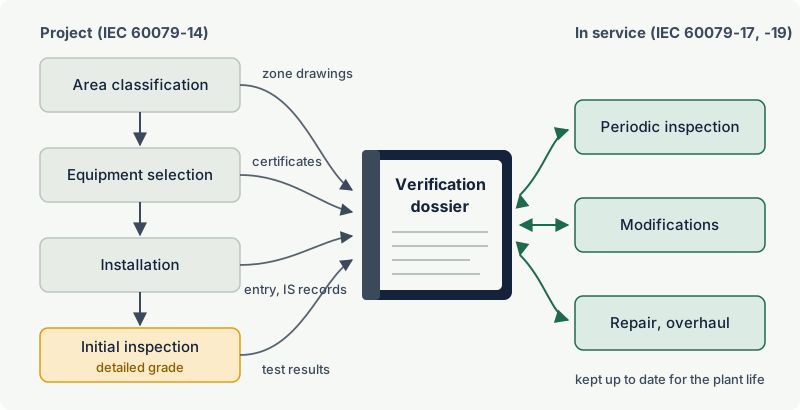
Regulators treat a missing dossier as a real finding. WorkSafe Victoria lists unavailable verification dossiers and hazardous zone maps among the failures it took enforcement action on at major hazard facilities.
Selecting equipment for the location
Selection is a matching exercise between the site information and the equipment marking. Every one of these checks must pass:
| Check | Site information | Equipment marking | Rule |
|---|---|---|---|
| Level of protection | Zone 0, 1, 2 (gas) or 20, 21, 22 (dust) | EPL Ga, Gb, Gc or Da, Db, Dc | Zone 0 needs Ga; Zone 1 Ga or Gb; Zone 2 Ga, Gb or Gc (same pattern for dust) |
| Group | Gas group IIA, IIB, IIC; dust group IIIA, IIIB, IIIC | Equipment group | Equipment group equal to or higher than the substance group |
| Temperature | Autoignition temperature; dust cloud and layer ignition temperatures | T class or maximum surface temperature | Surface temperature below the ignition temperature (with the dust margins) |
| Ambient | Lowest and highest site ambient | Rated ambient range (-20 °C to +40 °C where older equipment marks no range; IEC 60079-0 edition 8 requires the range always to be marked) | Site range within the rated range |
| External influences | Corrosion, UV, vibration, water, chemicals, mechanical impact | IP rating, materials, certificate conditions | Suitable, or protected |
| Specific conditions | - | "X" on the certificate | Every condition met and recorded |
A higher group covers a lower one: IIC equipment may be used where IIB or IIA is required, and IIIC equipment where IIIB or IIIA is required. The temperature class works the other way round: T6 equipment (85 °C maximum) is acceptable where T3 (200 °C) is required. For the details see EPLs and zones, gas groups and temperature classes.
Example: A pump transferring toluene stands in Zone 1. Toluene is gas group IIA, temperature class T1 (autoignition temperature 530 °C). A motor marked Ex db eb IIB T4 Gb with a rated ambient of -20 °C to +40 °C passes every check: Gb suits Zone 1, IIB covers IIA, T4 (135 °C) is far below 530 °C, and the site ambient of -5 °C to +35 °C is inside the rated range. If the same pump later handled hydrogen (IIC), the motor would no longer be suitable even though its temperature class still is.
Uncertified, second-hand and repaired equipment can only be selected when its suitability is shown and documented. Rotating machines (including converter-fed motors), luminaires, heating systems, plugs and sockets, batteries, RFID tags, gas detectors and portable equipment have their own selection rules.
Designing the supply: protection, isolation and earthing
Electrical protection and isolation
Wiring must be protected against overload, short circuit and earth faults, so that a fault does not create a hot surface or an arc in the hazardous area. Rotating machines need overload protection. Electric heating systems need earth fault protection; the 2013 edition required a residual current device of 100 mA or less in TT and TN systems and insulation monitoring in IT systems.
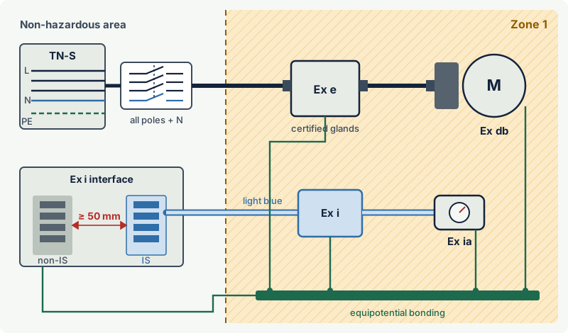
Each circuit or group of circuits needs a means of isolation that disconnects all live conductors, including the neutral, so that work can be done safely. The design must also provide emergency switch-off from a suitable place outside the hazardous area for equipment that must be de-energised quickly.
Type of system earthing
- TN systems: only TN-S is allowed in the hazardous area; the neutral and protective conductor must not be joined there. Any change from TN-C to TN-S is made outside the hazardous area. A PEN conductor carries load current, so a break or poor joint can make metalwork live or cause sparks at bonding points.
- TT systems: the earth electrode resistance limits the earth fault current, often too much for fuses or circuit breakers to clear a fault quickly, so protection relies on a residual current device; IEC 60079-14 calls for one where a TT system supplies Zone 1 equipment.
- IT systems: an insulation monitoring device must signal the first earth fault, so it is found and cleared before a second fault can cause arcing.
Equipotential bonding
All exposed and extraneous conductive parts in the hazardous area are bonded to an equipotential bonding system, so that no spark can occur between metal parts at different potentials. An enclosure firmly fixed to bonded steelwork with good metallic contact need not have its own bonding conductor, but cable armour and metal conduit must be included. Bonding connections must resist loosening and corrosion; the 2013 edition set 4 mm² copper as the minimum for supplementary bonding connections. Cathodically protected parts, lightning and static electricity have their own rules. See earthing, bonding and equipotential bonding.
Wiring systems and cable entries
Cables
Cables for fixed wiring must suit the conditions of service, resist flame propagation, and be protected against mechanical damage, corrosion, chemicals, heat and UV along their whole route. The usual types are cables with a thermoplastic, thermosetting or elastomeric sheath, and mineral insulated metal-sheathed cables. The 2013 edition defined the sheathed cables as circular and compact, with an extruded bedding or sheath and non-hygroscopic fillers; this matters because a cable with voids or absorbent fillers can carry gas from one enclosure to another, or out of a flameproof enclosure. The 2024 edition added requirements for cables under thermal insulation and for overhead wiring.
Other wiring rules that inspectors check often:
- Unused cores must be connected to earth or insulated with terminations suitable for the type of protection; tape alone is not acceptable insulation.
- Joints in a hazardous area should be avoided. Where unavoidable they must be made in an enclosure suitable for the zone, or with a method suitable for the mechanical, electrical and environmental stresses.
- Openings in walls and floors between areas of different classification must be sealed so that gas, vapour or liquid cannot pass through cable trenches, ducts or conduits from a hazardous to a non-hazardous area.
- Flexible cables for portable and transportable equipment must be of a heavy duty type suited to the hazards of the location.
- Aluminium conductors have their own termination rules.
Conduit systems
Where conduit is used, it becomes part of the protection: sealing devices stop gas and flame passing along it into or out of a flameproof enclosure, drains stop condensation collecting, and threads and fittings must be suitable and tight. See zones vs divisions for how this differs from NEC practice.
Cable entries and unused openings
The cable entry is the one part of the protection the installer builds on site, so it is where most installation errors happen. The general rules are:
- The entry device must keep the type of protection of the enclosure (Ex d, Ex e, Ex t, Ex nR and so on) and must be certified for it.
- The gland must fit the cable diameter. Building up a thin cable with tape or heat-shrink sleeves to fit a larger gland is not allowed.
- Cables must be clamped so that pull and twist are not transmitted to the terminations; where extra clamping is needed, the 2013 edition recommended a clamp within 300 mm of the gland. The cable should leave the gland straight.
- Additional entries may only be made where the manufacturer's documentation permits them, in the stated positions and sizes. An installer must never drill a flameproof enclosure.
- Unused openings must be closed with blanking elements suitable for the type of protection, removable only with a tool, giving at least IP54 or the IP required by the location, whichever is higher. Plastic transit caps are not blanking elements.
- On flameproof enclosures, thread adapters must not be combined with blanking elements.
For flameproof enclosures the choice between a gland with an elastomeric seal and a barrier-type entry device (compound-filled around the individual cores) follows a flowchart. In the 2024 edition it is based on the gas group, the length of cable connected and the free volume of the enclosure, with a new normative cable test as evidence where needed. The details are explained in cable glands for hazardous areas.
Rules for specific types of protection
Flameproof "d"
Keep solid obstacles away from flanged flamepaths: unless the certificate allows less, the minimum distance is 10 mm for IIA, 30 mm for IIB and 40 mm for IIC. Protect flamepaths against corrosion with non-setting grease or the agent named by the manufacturer, never with hardening compounds, paint or extra gaskets. See flameproof enclosures.
Increased safety "e" and "n"
Terminals are certified for a defined range of conductor sizes and numbers of conductors per clamp, and junction boxes for a maximum combination of terminals, conductors and current (because of heat dissipation). The installer must stay within these limits and keep the IP rating, normally at least IP54 for increased safety terminal boxes. See increased safety (Ex e).
Pressurisation "p", rooms and analyser houses
Pressurised equipment needs its protective gas supply, purge and alarm or trip arrangements installed as specified. The 2024 edition added clauses for pressurised rooms and analyser houses; see pressurised rooms and analyser houses.
Intrinsically safe installations
Intrinsic safety (Ex i) limits energy, so the wiring itself is part of the protection:
- System documentation. Every intrinsically safe circuit needs a descriptive system document (or system certificate) showing that the apparatus, associated apparatus and cable are safe together. Cable capacitance and inductance count against the limits, so a long run can make a loop unsafe. See IS loop verification.
- Insulation. Cables for intrinsically safe circuits must have insulation rated for a dielectric test of at least 500 V between conductors, screen and earth; the standard sets the exact test requirement, so check it against the cable data sheet.
- Separation. Intrinsically safe circuits must be kept apart from other circuits so that energy cannot be induced or transferred into them. At terminals, 50 mm separation between the bare parts of intrinsically safe and non-intrinsically safe terminals, or a suitable partition, is the usual arrangement.
- Identification. Intrinsically safe cables, terminals and junction boxes must be identifiable; where a colour is used to identify them, IEC 60079-14 calls for light blue.
- Earthing. An intrinsically safe circuit is either isolated from earth or earthed at one point only. Shunt-diode (zener) barriers rely on a high-integrity earth connection. Cable screens are normally earthed at one point.
- Simple apparatus. Passive devices such as switches, thermocouples, RTDs and junction boxes may be used without certification if they meet the simple apparatus rules (the 2024 edition added a normative annex with additional requirements for simple apparatus).
See intrinsic safety and zener barriers vs galvanic isolators.
Initial inspection and handover
Before first use, the installation receives an initial inspection at detailed grade: enclosures are opened (isolated), terminations, entries and flamepaths are checked, and insulation resistance, earth loop impedance or earth resistance and protection settings are tested. The 2024 edition gives this its own clause, with informative tables for Ex d, e, n, t, i, p and o installations aligned with IEC 60079-17.
The results are recorded and added to the verification dossier. From that point on, the installation is maintained and inspected under IEC 60079-17.
Who may do the work
IEC 60079-14 requires designers, installers and inspectors to be competent, describes the knowledge and skills for each role in a normative annex, and expects competence to be documented. The IECEx Certificate of Personnel Competence (CoPC) scheme is one way to show it; its units include Ex 003 (install explosion-protected equipment and wiring systems), Ex 008 (perform detailed inspection) and Ex 009 (design electrical installations). See competence of people working in hazardous areas.
Practical case: a new metering skid in Zone 1
A contractor installs a gas metering skid in a Zone 1 area classified for natural gas (methane, IIA, T1, autoignition temperature about 600 °C):
- Documents. Area drawing, certificates, instructions and the IS descriptive system document are collected before work starts.
- Selection. Every item needs EPL Gb or better, group IIA or higher and an ambient rating covering the -15 °C winter minimum. One junction box rated -10 °C to +40 °C fails and is replaced.
- Supply and entries. The skid is fed from a TN-S board through all-pole isolators. Each gland is matched to the cable and the protection type, the entry selection for the flameproof motor is recorded, and unused entries get certified blanking elements.
- Intrinsic safety. Light blue IS cables run on a separate tray section, and the loop calculation uses the real 180 m cable length.
- Initial inspection. A detailed inspection finds two terminals carrying more conductors than the terminal certificate allows; they are corrected and the records go into the dossier.
Common mistakes
- Treating certification as enough. A certified device installed with the wrong gland, an open entry or a missing bond is no longer protected. The installation must match the certificate and the instructions.
- Ignoring the ambient range. Equipment rated -20 °C to +40 °C is not automatically suitable for a desert skid or an arctic site. Check the rated range against real site temperatures, including solar heating.
- Using a PEN conductor in the hazardous area. TN-C or TN-C-S arrangements must change to TN-S before the hazardous area.
- Leaving the dossier for later. Without certificates, entry selection records and inspection records, nobody can prove the installation is safe, and future inspectors cannot check it properly.
- Skipping the initial inspection because the equipment is new. Most defects found at commissioning are installation defects, not equipment defects.
- Applying IEC 60079-14 to mechanical equipment. Pumps, gearboxes and couplings fall under ISO 80079-36 and -37; see non-electrical equipment.
Frequently asked questions
What is IEC 60079-14 used for?
IEC 60079-14 is used to design, select, install and initially inspect electrical installations in hazardous areas where flammable gas, vapour or combustible dust may form an explosive atmosphere. It applies in addition to the normal electrical installation rules. In Europe it is published as EN IEC 60079-14 and is widely used to meet the installation duties under the ATEX workplace directive.
What is the latest edition of IEC 60079-14?
The latest edition is IEC 60079-14:2024, edition 6, published in August 2024. It replaced the 2013 edition and was adopted as EN IEC 60079-14:2024 in October 2024, with conflicting national standards to be withdrawn by October 2027.
What is a verification dossier?
A verification dossier is the set of documents showing that the electrical equipment and installation in a hazardous area comply with the requirements. It contains the area classification, the equipment certificates and instructions, installation records such as cable entry selection and circuit schedules, intrinsic safety documents and inspection records, and it must be kept up to date for the life of the installation.
Is TN-C-S allowed in a hazardous area?
Not inside the hazardous area. IEC 60079-14 requires a TN system to be TN-S within the hazardous area, with separate neutral and protective conductors. A TN-C supply can feed the site, but the change to TN-S and the bonding connection must be made outside the hazardous area.
Does IEC 60079-14 require an initial inspection?
Yes. Every new installation must have an initial inspection before it is put into service, at detailed grade. The 2024 edition gives it a dedicated clause and informative inspection tables; the results become part of the verification dossier.
Related on excodex
- Cable glands for hazardous areas: barrier glands, compound glands and selection
- Inspection of Ex installations under IEC 60079-17
- Common Ex inspection findings and how to fix them
- Earthing, bonding and equipotential bonding in hazardous areas
- How to read an Ex marking and the Ex marking check tool
- Standards space: IEC 60079-14, IEC 60079-17, and the forum
Standards and further reading
- IEC 60079-14:2024, Explosive atmospheres, Part 14: electrical installations design, selection and installation of equipment, including initial inspection (edition 6). Preview with contents and the table of significant changes: IEC 60079-14:2024 sample pages
- EN IEC 60079-14:2024, European adoption: catalogue entry with scope, dates and superseded standard
- IEC 60079-17, inspection and maintenance of electrical installations
- IEC 60079-0, equipment general requirements; IEC 60079-11, intrinsic safety; IEC 60079-1, flameproof enclosures; IEC 60079-7, increased safety
- IEC 60079-10-1 and IEC 60079-10-2, classification of areas
- P. Thurnherr (convenor of IEC maintenance team MT 60079-14), "Electrical installations: design, selection, erection and inspection", IECEx International Conference 2014, Kuala Lumpur, presentation on the requirements of IEC 60079-14 edition 5: conference slides
- WorkSafe Victoria, "Management of electrical equipment in hazardous areas at major hazard facilities" (2020): guidance PDF
- IECEx Certified Persons scheme and units of competence: IECEx CoPC overview
This article is general technical information prepared by the excodex editorial team. It does not replace the applicable standards, the equipment certificates and instructions, national regulations or the assessment of a competent person.