Pressurised rooms and analyser houses: making an area non-hazardous by ventilation
Abstract
How IEC 60079-13 protects rooms in hazardous areas: pressurisation pb and pc at 25 Pa, artificial ventilation vc, purging with 10 room volumes, door rules, gas detection at 25 % of the limiting value, alarms and analyser houses, with a worked example.
A room standing in a hazardous area can hold ordinary, non-Ex equipment if it is protected in one of two ways defined by IEC 60079-13. Pressurisation keeps the outside atmosphere out: clean air from a safe location holds the room at least 25 Pa above its surroundings, after a purge of normally ten room volumes, with level pb for Zone 1 or 21 and pc for Zone 2 or 22. Artificial ventilation (level vc) dilutes a release inside the room, such as a leak from an analyser sample line, so that the concentration stays below 25 % of the lower flammable limit. Both depend on monitoring: pressure or flow sensors, gas detectors set at 25 % of the limiting value, alarms, and defined actions such as power isolation when the protection fails.
This article explains pressurised and artificially ventilated rooms, the purge, doors and airlocks, gas detection interlocks and alarms, and how analyser houses combine the two techniques, with a worked example.
Key points
- IEC 60079-13:2017 covers rooms people can enter, from a single room to a complete building, including their inlet and outlet ducts; an acoustic hood designed for personnel entry can count as a room, while pressurised equipment enclosures that people do not enter are covered by IEC 60079-2.
- Pressurisation pb gives EPL Gb or Db and allows unprotected equipment in a room located in Zone 1 or 21; pc gives EPL Gc or Dc for Zone 2 or 22. Artificial ventilation vc gives EPL Gc.
- A pressurised room must hold at least 25 Pa above adjacent spaces with half of its outlets (not doors) open, and loss of pressure below 25 Pa counts as failure.
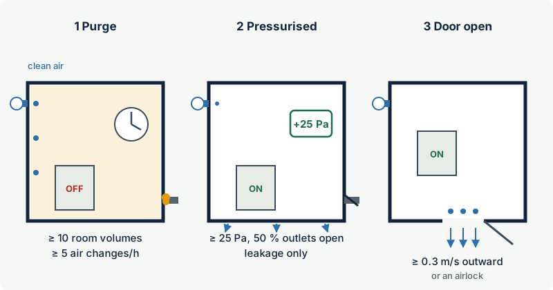
- Before non-Ex equipment is switched on, the room is purged with clean air until gas is at most 25 % of the limiting value: normally a minimum of 10 room volumes at a rate of at least five air changes per hour, unless a smaller purge is proven by test.
- Doors used for entry need an airlock or an outward air velocity of at least 0.3 m/s through the open door.
- For pb, failure of pressurisation must switch off equipment without a suitable EPL automatically, unless operation continues under defined administrative controls; for pc, power may stay on for a limited time.
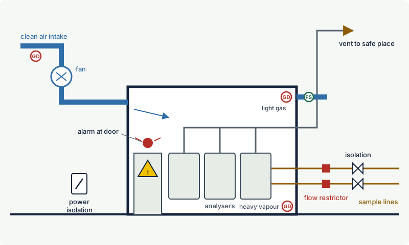
- Analyser houses usually combine a clean air supply with ventilation of internal sources, flow-restricted and isolatable sample lines, vents piped to a safe place, gas detection and alarms; IEC 61285 deals with their safety.
Rooms, not enclosures: where IEC 60079-13 fits
Pressurisation as a type of protection is familiar from equipment: a cabinet with type of protection "p" under IEC 60079-2, where protective gas keeps the outside atmosphere out (see pressurisation Ex p). IEC 60079-13 applies the same idea to rooms that people enter: control rooms, switchrooms, analyser houses, metering houses, quality laboratories and gas turbine enclosures.
The current edition is IEC 60079-13:2017, the second edition, which introduced artificial ventilation "v" alongside pressurisation and replaced the earlier levels px, py and pz with pb and pc. Rooms protected with inert or flammable gas are outside its scope. A third edition was circulated as a committee draft for vote in 2025; among other changes it covers analyser houses explicitly and is set to replace the old technical report on analyser house ventilation, IEC 60079-16.
Pressurisation or artificial ventilation?
The two techniques solve different problems:
| Pressurisation pb | Pressurisation pc | Artificial ventilation vc | |
|---|---|---|---|
| Protects against | outside atmosphere entering | outside atmosphere entering | a release inside the room |
| Room located in | Zone 1, 2, 21 or 22 | Zone 2 or 22 | Zone 2, or a non-hazardous area with an internal source |
| EPL provided | Gb or Db | Gc or Dc | Gc |
| Internal source of release | not allowed with pressurisation alone | not allowed with pressurisation alone | yes, that is its purpose |
| Clean air from | a non-hazardous area | may be a Zone 2 area, with conditions | a non-hazardous area, or Zone 2 with conditions |
| Main monitored value | pressure differential, purge flow | pressure differential, purge flow | ventilation flow |
A room in a hazardous area that also contains an internal source, typical of analyser houses, needs both: pressurisation to keep the outside out, and ventilation to dilute what leaks inside. The standard then applies the requirements of both techniques.
Pressurised rooms
Clean air supply
For pb, the air must come from a non-hazardous area. For pc, the intake may be in a Zone 2 area if the air is essentially clean in normal operation. Whenever the intake is in Zone 2, IEC 60079-13 adds conditions: at least one flammable gas detector with alarm in the air intake and at least one in the room, automatic shutdown of the intake when the intake detector reaches 25 % of the limiting value, and an EPL suitable for the unprotected area for the detectors, alarm and interlock equipment, and the fan and its motor.
A clean air duct running through a hazardous area must stay above atmospheric pressure along its whole length, so that leaks flow outwards. Any outdoor air used by heating, ventilation and air conditioning equipment must come from the clean source. The pressurisation system must be powered independently of the electrical supply to the room.
Overpressure
The pressurisation system must be able to hold at least 25 Pa in the room relative to adjacent spaces with 50 % of all outlets (other than doors) open; a pressure differential below 25 Pa is the failure criterion. A sensor in the room detects the loss and must be able to raise an alarm; a flow sensor at the fan discharge must detect loss of air flow and raise an alarm.
For comparison, pressurised equipment enclosures under IEC 60079-2 need 50 Pa for levels pxb and pyb; for rooms, the lower value is combined with door rules and alarms.
Doors and airlocks
Doors are the weak point of a pressurised room: opening one can collapse the overpressure. IEC 60079-13 requires entry doors to be self-closing, close fitting and able to close and latch against the pressure differential, and requires one of two measures to keep the outside atmosphere from entering through an open door:
- An airlock: two interdependent doors. The airlock needs either a continuous flow of clean air of at least five airlock volumes per hour, or gas detectors in the airlock that alarm at 25 % of the limiting value. Indicators in the room should show when the airlock doors are not closed, electrical equipment in the airlock must suit the outside EPL, and signs remind people to close one door before opening the other.
- Outward air velocity: without an airlock, at least 0.3 m/s through the open door, measured with 50 % of the other openable outlets open. The pressure may drop below 25 Pa while the door is open, as long as this velocity is maintained. The 0.3 m/s figure is based on low wind and may need to be higher at exposed sites.
Doors marked for restricted access, equipment and maintenance doors kept closed under management control, and emergency exits that open only from inside are exempt.
Purging before switching on
Before any equipment without a suitable EPL is energised, flammable gas in the room must be brought to not more than 25 % of the limiting value by purging with clean air. The limiting value is the lowest LFL among the flammable components involved, considering the most onerous concentrations that can occur.
- The purge volume is a minimum of 10 room volumes, room volume meaning the empty room plus its ducts, unless a smaller volume is verified by the smoke test or other analysis.
- The purge flow is at least five air changes per hour.
- Purging is verified by flow measurement at a dedicated outlet, or by room pressure combined with outlet flow sensing or with gas detectors. Gas detection cannot reduce the initial purge, but it can be used to extend it.
- Any enclosure inside the room that exceeds 5 % of the room volume and contains non-Ex equipment must be vented, purged or pressurised itself. Top and bottom vents of at least 1 cm² per 1000 cm³ of enclosure volume, and not less than 6.3 mm in diameter, are commonly considered sufficient.
- Dead spaces such as suspended ceilings, raised floors and trenches should be avoided, because they are hard to purge.
For pb, the purge sequence must be automatic: the timer starts only when purge flow and minimum pressure are established, and equipment may be switched on when the time has elapsed. If a step fails, the cycle restarts. If pressure is lost while a door switch shows a door open, the timer pauses; if the loss lasts more than 60 s, the purge starts again regardless. Purging is needed at first commissioning and after any loss of pressurisation; administrative controls can be accepted after short, uneventful losses, but the means to purge must exist.
Combustible dust cannot be purged out; dusty rooms must be cleaned before equipment without a suitable EPL is energised.
When pressurisation fails
| Level | Required action on failure | Alternatives the standard accepts |
|---|---|---|
| pb | automatic switch-off of all equipment in the room that is not EPL Ga or Gb (Da or Db for dust) | continued operation under administrative controls, for example for a short time while a door is open and gas detectors confirm the room is below 25 % of the limiting value, or where immediate shutdown would create a more hazardous condition |
| pc | power may stay on for a limited duration; if pressurisation is not restored, switch off equipment that is not EPL Ga, Gb or Gc (or the dust equivalents) | administrative controls, for example confirmation by gas detection that the area outside has not exceeded 40 % of the limiting value, or work under permit |
The control system of the safety devices must tolerate a single fault for pb and be reliable in normal operation for pc; IEC 61508 and IEC 61511 can be used. The standard also asks for measures against ignition after shutdown, for example hot surfaces that stay above the ignition temperature, and recognises that some circuits, such as fire and gas detection and essential plant controls, may need to stay energised with additional layers of protection.
Artificially ventilated rooms
Artificial ventilation protects against a release inside the room. The design logic is set out in the standard:
- Classify the room first without ventilation, so that the required safety measures can be determined.
- Design the ventilation to control the internal sources, using IEC 60079-10-1 for the flow rate and arrangement, and keep the protected area below 25 % of the LFL.
- Limit the sources: keep stocks of flammable gas or liquid outside, make every pipe that brings a flammable substance into the room isolatable from outside, keep pipe sizes to the minimum, and use pressure relief devices and flow restrictors to limit any escape.
- Discharge the diluted air to the open air, away from clean air intakes and from places where it could pocket. For local extraction, the whole duct must run below atmospheric pressure, with the fan outside the room.
When ventilation fails, the standard links the action to the EPL the room would need without ventilation:
| EPL needed inside without ventilation | Equipment inside | Action on loss of ventilation |
|---|---|---|
| Gb | not Ex rated | isolate power or the internal source of release |
| Gb | EPL Gc | alarm; shut down power or the source after a limited time, unless gas detection or backup ventilation is provided (not for local ventilation) |
| Gc | not Ex rated | alarm; shut down power or the source after a limited time, with the same exceptions |
Where loss of ventilation could lead to a build-up of gas, audible and visual alarms must warn people not to enter, and the alarm must be audible inside so that people leave. For continuous or primary internal sources, the ventilation is tested by running the process under normal conditions for at least 5 minutes and confirming that the concentration stays below 25 % of the LFL; for secondary sources, calculation or modelling may be used.
Gas detection interlocks, alarms and marking
Gas detection appears throughout IEC 60079-13, almost always with the same threshold: 25 % of the limiting value.
| Detector location | Purpose | Typical action at 25 % of the limiting value |
|---|---|---|
| Air intake in a Zone 2 area | prove the supply air is clean | alarm and shut down the intake |
| Inside a pressurised room | confirm a safe atmosphere during delays, after purging, or when the intake is in Zone 2 | alarm; supports administrative controls instead of immediate shutdown |
| Airlock without continuous flow | detect gas carried in by people | alarm |
| Inside a ventilated room | verify dilution of internal releases | isolate power or the supply of flammable substance |
The type, number and location of detectors come from a process risk evaluation and the IEC 60079-29 series of gas detection standards. No standard sets one fixed mounting height: detectors normally go near the ceiling for light gases such as methane or hydrogen and low down for heavy vapours such as propane, but the right position follows the likely release, the gas behaviour and the airflow (IEC 60079-29-2). All safety devices, including detectors, the fan and its motor, must be suitable for the area as if the room had no protection, because they must work when it fails.
Alarms must be placed where responsible staff will notice them. The standard also requires clear marking: the type of room, the volume, minimum purge flow and duration, the minimum pressure differential or ventilation flow, a warning at the isolating switch to run the purge for the stated time before energising, "keep door closed" notices, restricted access markings, airlock instructions, and a danger notice at each entrance where an alarm means a flammable build-up inside. A functional sequence diagram (truth table, state diagram or flow chart) of the control system must be part of the documentation and verified by functional tests.
Analyser houses
An analyser house (analyser shelter) brings process samples to analysers inside a building, usually located in a hazardous area. It therefore has both problems at once: the outside atmosphere must be kept out, and the samples are internal sources of release.
IEC 61285:2015 (third edition), Industrial-process control: Safety of analyser houses, sets physical safety requirements for analyser houses covering fire, explosion and health hazards, including toxic and asphyxiant gases, for houses with internal or external explosive atmospheres. In North America, NFPA 496 (2024 edition) covers purged and pressurised control rooms and analyser rooms containing sources of flammable gas, UL 60079-13 adopts IEC 60079-13 with US differences, and API RP 555 deals with process analyser systems.
A typical analyser house combines:
- a clean air supply from a safe location, often with a gas detector at the intake, giving pressurisation and continuous ventilation at the same time;
- sample lines with isolation valves and flow restrictors outside the house, so that the largest possible internal leak is limited and can be stopped without entering;
- pressure reduction before the sample enters, which reduces the leak rate in proportion to the absolute pressure;
- vent and bypass lines piped to a vent header that discharges to a safe place, not inside the house;
- gas detectors inside, located by gas density, and toxic or oxygen detectors where samples contain toxic gases or inert carrier gases;
- alarms at the door and inside, power isolation from outside, and signs at the entrances.
Toxic gases often decide the design: a sample of hydrogen sulphide-bearing gas can be dangerous to people at concentrations far below its LFL, so dilution to below 25 % of the LFL is not enough on its own.
Worked example: an analyser house for natural gas
The values are illustrative, not design values. A 4 m × 3 m × 3 m analyser house (36 m³) stands in a Zone 2 area and houses gas chromatographs analysing natural gas, treated as methane (LFL 4.4 % by volume). Sample lines arrive at 10 barg. Clean air is supplied from a non-hazardous area at 20 air changes per hour: 720 m³/h, or 0.2 m³/s.
Purge. Ten room volumes are 360 m³. At 720 m³/h the purge takes 30 minutes. At the minimum rate of five air changes per hour it would take two hours, which is why designers usually purge at a much higher rate than the minimum.
Internal leak. The design case is a sample line that breaks inside the house, with the release limited by the restrictor outside. The flows below assume choked flow of methane at 15 °C with a discharge coefficient of 0.99 (a conservative choice for a machined orifice). With mixing assumed moderately poor (f = 2), the background concentration is about 2 × gas volume flow ÷ air flow:
| Restriction on each sample line | Methane flow at 10 barg | Background concentration | Fraction of LFL |
|---|---|---|---|
| 0.5 mm orifice | about 1.3 kg/h | about 0.55 % by volume | about 12 % |
| 1 mm orifice | about 5.3 kg/h | about 2.2 % by volume | about 50 % |
| none, 4 mm tube bore | about 85 kg/h | far above the LFL | not controllable |
Example: Only the 0.5 mm restrictor keeps the room below 25 % of the LFL with this ventilation. The 1 mm restrictor would need at least twice the air flow; an unrestricted line cannot be controlled by any practical ventilation. Reducing the sample pressure outside the house, for example to 2 barg, would cut each flow by a factor of about 3.7 (11 bar absolute down to 3 bar absolute).
Door. A single 0.9 m × 2.0 m door kept at 0.3 m/s outward needs 0.54 m³/s, about 1,950 m³/h, nearly three times the design air flow. An airlock, or a restricted-access door used only under control, is therefore the usual choice.
Detection and alarms. Detectors at high level (methane is lighter than air) alarm and isolate the sample supply and the power to non-Ex equipment at 25 % of the limiting value; the intake detector shuts the intake if gas from the surrounding Zone 2 reaches it.
Common mistakes
- Opening doors as if the room were ordinary. Wedged or frequently used doors without an airlock destroy the overpressure. Design the access arrangement for how people actually use the building.
- Forgetting the purge after a stop. After a loss of pressurisation the room must be purged before non-Ex equipment is re-energised, unless defined administrative controls apply. Manual bypasses of the purge timer defeat the protection.
- Locating the air intake in or near a hazardous area without detection. Clean air must be clean. Intakes downwind of vents, near loading points or below grade can draw gas in.
- Unrestricted sample lines. Without a flow restrictor and an outside isolation valve, the largest internal leak can overwhelm any ventilation.
- Safety devices that are not Ex rated. Fans, motors, detectors and the pressurisation controller must work when protection has failed, so they need an EPL suitable for the unprotected area.
- Modifying the room without review. New cable penetrations, extra equipment cabinets or a new door change leakage and purge behaviour. IEC 60079-13 requires the documentation to be revised after modifications.
Frequently asked questions
What pressure is required in a pressurised room?
IEC 60079-13 requires the pressurisation system to maintain at least 25 Pa in the room relative to adjacent spaces, with half of the outlets (not doors) open. A pressure below 25 Pa is treated as failure of the pressurisation system and must be detected and alarmed.
How long must a pressurised room be purged?
Until gas inside is at most 25 % of the limiting value. The standard sets a minimum purge of 10 room volumes, including ducts, at a flow of at least five air changes per hour, unless a smaller purge volume is verified by a smoke test or analysis. The resulting purge time must be marked at the isolating switch.
What is the difference between a pressurised room and an artificially ventilated room?
A pressurised room keeps an outside explosive atmosphere from entering by holding a clean-air overpressure. An artificially ventilated room dilutes a release from a source inside it so that the concentration stays well below the LFL. Analyser houses in hazardous areas usually need both.
Is a control room in a hazardous area allowed?
Yes, if it is protected, for example as a pressurised room to IEC 60079-13 or NFPA 496, with clean air from a safe location, door arrangements, monitoring and defined actions on failure. Many operators prefer to locate control rooms outside hazardous areas altogether, which avoids these measures.
At what level should gas detectors in an analyser house trip?
IEC 60079-13 uses 25 % of the limiting value, the lowest LFL of the flammable components, for alarms and for isolating power or the flammable supply in ventilated rooms. Toxic samples may require much lower set points based on exposure limits, using separate toxic gas detectors.
Related on excodex
- Pressurisation (Ex p): px, py and pz, purging and protective gas
- Ventilation in area classification: degree of dilution and availability
- Estimating the extent of a hazardous zone: release rates and dilution
- Fixed gas detection systems: design principles and when they are required
- Where to install gas detectors: height, distance and common mistakes
- Equipment Protection Levels (EPL): Ga, Gb, Gc, Da, Db, Dc and how they match zones
- Tools: gas and solvent library, standards spaces IEC 60079-13, IEC 60079-2, IEC 60079-10-1, IEC 60079-29-0, forum
Standards and further reading
- IEC 60079-13:2017 (edition 2), Explosive atmospheres, Part 13: Equipment protection by pressurized room "p" and artificially ventilated room "v". Text of the bilingual 2018 printing incorporated by reference in US federal regulations: law.resource.org; IEC webstore (current edition, IEC 60079-13:2017): webstore.iec.ch
- Draft third edition of IEC 60079-13 (CENELEC enquiry draft, prEN IEC 60079-13): catalogue entry with summary of changes
- IEC 60079-2, equipment protection by pressurized enclosure "p", for equipment enclosures.
- IEC 61285:2015 (edition 3), Industrial-process control: Safety of analyser houses: preview
- NFPA 496 (2024 edition), Standard for purged and pressurized enclosures for electrical equipment, including control rooms and analyser rooms: document listing
- UL 60079-13, second edition (2022), US adoption of IEC 60079-13 with national differences: ANSI webstore
- API RP 555, Process Analyzers, third edition.
- IEC 60079-10-1, classification of areas, used to size ventilation for internal sources.
This article is general technical information prepared by the excodex editorial team. It does not replace the applicable standards, the equipment certificates and instructions, national regulations or the assessment of a competent person.