Where to install gas detectors: height, distance and common mistakes
Abstract
Gas detectors must sit where the gas actually goes: near likely leak sources, high for light gases, low for heavy ones, in the path of air movement and within reach for testing. How density, release, ventilation, coverage and mapping studies decide placement.
Gas detectors must be installed where the gas will actually go between its release point and the people or ignition sources it threatens. In practice that means close to the likely leak sources, at the height where the gas collects (high for lighter-than-air gases such as hydrogen and methane, low for heavier-than-air gases and vapours such as propane and solvent vapours), in the path of the air movement rather than in front of fresh-air inlets, and where the detector can be reached for testing. There is no single correct height or spacing: placement follows from the gas properties, the release conditions, the ventilation and the purpose of each detector, and for large plants it is checked with a detector mapping study.
This article explains each placement factor, the coverage concepts used in mapping studies, practical examples for typical installations and the mistakes found most often on site.
Key points
- Start with the purpose of each detector: early leak detection at a source, accumulation in an enclosure, protection of an air intake or ignition source, or a boundary. The purpose decides the location.
- Density relative to air sets the starting height. IEC detector guidance has treated gases with relative density below about 0.8 as lighter than air and above about 1.2 as heavier, with both cases to be considered in between.
- Release conditions can override density: high-pressure jets go where they are pointed, cold vapours (for example from LNG) sink until they warm, and hot releases rise.
- Ventilation and wind usually move gas more than buoyancy does. HSE describes ventilation surveys as critical to detector performance.
- Gas detection is not as effective as often assumed: an HSE review of eight years of UK offshore release data found an effective detection rate of about 60 %.
- Coverage can be assessed geographically (can a defined cloud exist anywhere without being detected?) or by scenarios (what fraction of realistic leaks are detected?).
- A detector that cannot be reached for bump testing and calibration will not be tested properly; access is a placement criterion, not an afterthought.
Start with the purpose of each detector
Before choosing a height, decide what each detector is for. A typical installation mixes several purposes:
| Purpose | Where detectors go | Typical example |
|---|---|---|
| Early leak detection | Close to the release sources identified in the area classification | Pump seals, compressor packing, flanges, valve stems, sample points |
| Accumulation in an enclosure | Where gas collects inside the building or module | Compressor house roof apex, analyser house, battery room ceiling |
| Protection of air intakes and ignition sources | In the intake or close to it | Ventilation air intakes, gas turbine combustion air, fired heater areas |
| Perimeter or boundary | Along the edge of the process area | Open path detectors between process units and occupied areas |
| Personnel exposure (toxic gases) | Where people breathe and work | H2S around wellheads, sour water units |
Writing the purpose next to each tag number in the detector schedule makes the design reviewable: every detector should answer the question "which release is this one for?"
Factor 1: gas density and temperature
Light, heavy and neutral gases
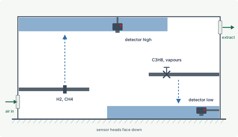
Relative density (vapour density compared with air, air = 1) tells you which way a gas tends to move once it has lost its release momentum and mixed little with air:
| Gas | Relative density (air = 1) | Tendency | Detector height (starting point) |
|---|---|---|---|
| Hydrogen | 0.0696 | Rises fast | High, at ceiling or roof apex |
| Methane (natural gas) | 0.554 | Rises | High |
| Ammonia | 0.588 | Rises when warm and dry | High, but see cold releases below |
| Acetylene | 0.899 | Close to neutral | High and low |
| Carbon monoxide | 0.967 | Neutral | Breathing zone and near sources |
| Ethylene | 0.968 | Neutral | High and low, near sources |
| Hydrogen sulfide | 1.18 | Slightly heavy | Low and breathing zone |
| Propane | 1.52 | Sinks | Low, pits and trenches |
| Butane | 2.01 | Sinks | Low |
| Toluene vapour | 3.18 | Sinks, spreads along floor | Low, near spill and pool areas |
The IEC selection guide for flammable gas detectors (IEC 60079-29-2, in its first edition) suggested treating gases below about 0.8 as lighter than air and above about 1.2 as heavier than air, and considering both possibilities for gases in between. It also described the basic behaviour in still air: a light gas tends to fill the space from the release point up to the ceiling, a heavy gas from the release point down to the floor. More detail on density is in vapour density: which gases rise and which sink.
Temperature changes the picture
Density at room temperature is only a starting point. The temperature of the released gas matters as much:
- Cold releases sink. Vapour from liquefied natural gas is heavier than air when it first evaporates; the US NOAA gives about -106 °C as the temperature below which LNG vapour is heavier than air. A methane detector mounted only at roof level would miss the early, cold part of an LNG release.
- Flashing liquefied gases form dense clouds. Pressurised or refrigerated liquids such as ammonia and propane flash on release into a cold mixture of vapour and droplets that behaves as a heavy gas near the source, even when the pure gas would be light (ammonia) at room temperature.
- Hot releases rise. A hot vapour can rise even if its density at ambient temperature is higher than air, as IEC guidance notes. Releases from hot process equipment, dryers or ovens may need detectors higher than the density alone suggests.
Factor 2: the release itself
The location and type of release decide where a flammable cloud forms first:
- High-pressure gas leaks from flanges, seals and small-bore fittings form momentum jets. Near the source, the jet goes where the hole points, regardless of density, and mixes quickly with air. Detectors must therefore be grouped around each significant source in three dimensions rather than lined up at one height. HSE guidance for offshore modules recommends a three-dimensional pattern of detector heads where a release can slump, for example the dense, cold cloud from a liquefied gas leak in an area with little air movement.
- Low-pressure leaks (tank vents, drains, slow seepage) have little momentum, so buoyancy and air movement dominate from the start. Here density-based heights work well.
- Liquid spills evaporate from a pool at ground level. Most vapours are heavier than air and spread along the floor, into drains, trenches and pits. Detectors belong near the possible pool area and in the low points the vapour will flow into.
Develop the layout from the release sources already listed in the hazardous area classification (see grades of release).
Factor 3: ventilation and air movement
In most real installations, air movement determines where gas goes more than density does.
Indoors and in enclosures
- Find the air paths. Mechanical ventilation creates flows from inlets to extracts and leaves dead zones where gas can accumulate. IEC guidance recommends siting detectors in dead spaces where gas may collect and notes that smoke tracers can show the air movement and the dead spaces. A simple smoke test during commissioning often moves detectors more than any calculation.
- Use the extract. Gas released inside a room is carried towards the extract, so a detector near the extract, or in the extract duct, sees releases from many parts of the room. In a duct, the gas is already diluted, so alarm set points should be as low as practicable, and high air velocities can affect the sensor and may need a shroud.
- Avoid fresh-air inlets. A detector in front of a supply grille measures clean air.
- Consider ventilation failure. If the ventilation stops, the gas behaves according to its density again. Where ventilation is a protection measure, detectors should work in both cases.
Outdoors and in process modules
- Wind changes direction. A detector placed only downwind of the prevailing wind leaves the source unprotected for much of the year. Surround important sources rather than relying on one direction.
- Congestion and confinement trap gas. Pipe racks, decks, walls and large equipment create pockets with low air speed where clouds build up; these are also the places where an ignited cloud produces the highest overpressure.
- Low wind is the critical case. Strong wind dilutes small leaks quickly; calm conditions allow the largest flammable clouds to form. HSE's offshore guidance states that real-time ventilation surveys are critical to detector performance and that they are rarely done.
Factor 4: access, environment and maintainability
A detector is only as good as its last test. The location must allow it to be tested and kept working:
- Access for testing. Bump testing and calibration need a person with test gas at the sensor, or a remote gas application line, or a remote sensor head with the transmitter at an accessible height. A detector 8 m up in a roof with no platform will not be tested at the required interval.
- Orientation. Point detectors are normally mounted with the sensor facing down, with the manufacturer's weather or splash guard, so rain, washdown water and dust do not collect on the sinter or optics.
- Environment. Stay within the detector's rated temperature, humidity and vibration limits. Avoid steam vents, washdown nozzles, direct solar heating, heavy dust and places where the sensor can be hit by vehicles or lifting operations.
- Sampling systems draw gas through tubes to a remote sensor. They suit inaccessible or very hot locations, but add transport time, and their filters, pumps and flame arresters can block with dust or condensate.
- Technology choice. The location also affects the sensor type. Catalytic sensors near silicone sources or in low-oxygen spaces, or IR sensors for hydrogen, fail regardless of position (see catalytic vs infrared detectors).
Coverage: how many detectors and how far apart?
Prescriptive rules and the 5 m grid
Many company standards and codes give prescriptive rules: a detector at every compressor, at every ventilation intake, or on a regular grid. The best known is the 5 m grid used offshore. Industry literature usually traces it to UK HSE offshore research of the early 1990s, which concluded that in congested modules, methane clouds smaller than about 6 m across were not expected to produce damaging overpressures; a 5 m grid aims to detect any cloud large enough to matter. HSE also refers to a joint industry project on gas build-up from high-pressure releases in offshore modules, which found that a 5 m point detector grid worked well for clouds forming within the module: doubling the spacing greatly increased detection times, while halving it only slightly reduced them. The same HSE guidance notes that the minimum spacing in congested areas is typically around 5 m. The 5 m figure is guidance for offshore methane; more reactive gases or more confined areas may justify closer spacing.
Grids are simple to check but say nothing about whether detectors match the actual sources and air paths.
Geographic and scenario coverage
Performance-based design asks how well a layout detects the hazards. Two measures are used, described in the ISA technical report ISA-TR84.00.07 on fire and gas system effectiveness:
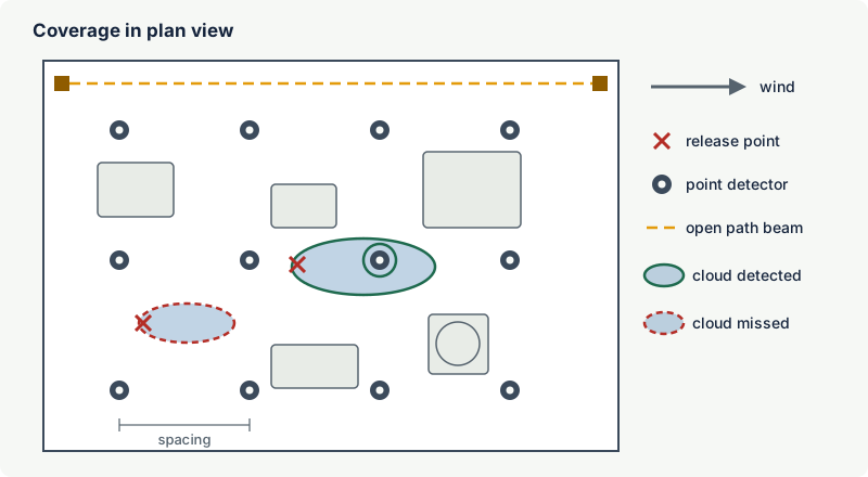
- Geographic coverage is the fraction of a monitored area or volume in which a gas cloud of a defined size, shape and concentration would be detected. The site's fire and gas philosophy defines the cloud.
- Scenario coverage is the fraction of realistic release scenarios (each with a hole size, direction, weather and frequency) whose clouds are detected. It needs dispersion modelling, often computational fluid dynamics (CFD), but it reflects how the plant really leaks.
Both can be calculated for one detector reaching alarm (1ooN voting) or for two detectors (2ooN), which is often required before automatic shutdown or deluge to avoid spurious trips. Two-detector coverage is always lower for the same layout. Coverage targets are set by the operator's risk assessment; industry literature quotes example targets of the order of 90 %, 80 % and 60 % for areas of decreasing risk grade, but these are examples, not requirements.
Why it matters
Fixed gas detection misses more releases than most people expect. HSE's offshore guidance quotes an analysis of eight years of hydrocarbon release data with an effective detection rate of about 60 %. A mapping study of a large onshore plant, published at the IChemE Hazards 28 symposium, found that the original layout, designed from company rules and engineering judgement, detected only about 12 % of the release scenarios in the pilot area; optimised layouts reached 70 to 80 %, and the detector count across the processing areas fell by about a fifth. More detectors are not the answer; better placed ones are.
Gas detector mapping studies
A mapping study is a structured check of whether a detector layout meets its coverage targets. A typical study:
- Defines the objective for each area: what gas, what hazard (explosion, toxic exposure, asphyxiation), what action the detection triggers and how much coverage is needed.
- Collects the inputs: release sources and their conditions, gas composition, ventilation or wind data, and a 3D model of the area including congestion.
- Defines the target clouds (geographic method) or the set of release scenarios with dispersion results (scenario method).
- Places detectors at feasible locations, taking access, mounting and technology into account, and calculates coverage for 1ooN and 2ooN voting.
- Iterates until the targets are met with a reasonable number of detectors, or records where they cannot be met and what other measures apply.
- Documents the results as coverage maps, detector schedules and the assumptions behind them.
- Verifies in the field after installation: ventilation measurements, smoke tests and a walk-down to confirm access and orientation.
Mapping is standard practice offshore, on large onshore plants and where gas detection is part of a safety instrumented function (see gas detection and functional safety). For a single building or small skid, a documented engineering assessment with a smoke test is often enough. Update the study whenever equipment, layout or ventilation changes.
Practical cases
Battery room or electrolyser enclosure (hydrogen)
Hydrogen rises quickly and collects at the highest point of the room. Detectors go at the ceiling, in the highest pocket between beams or in the roof apex, close to the extract and above the battery rows or the electrolyser stack. A detector beside the low-level air inlet is useless. The sensor must be hydrogen-capable (catalytic, thermal conductivity or electrochemical), since infrared sensors cannot detect hydrogen. See battery rooms and charging areas.
LPG pump and loading area (propane and butane)
Propane and butane are heavier than air, and their liquid releases flash into cold, dense clouds. Detectors go low, close to pump seals and loading arm connections, and at the low points where gas will flow: trenches, drains, pits and the downhill side of the slab. They must stay above the level of standing water and protected from vehicles. See fuel stations and LPG autogas.
Gas turbine or compressor enclosure (natural gas)
Methane is lighter than air, but inside a ventilated acoustic enclosure the forced airflow dominates. Detectors typically sit in the ventilation extract, which sees releases from anywhere in the enclosure (with low alarm levels, because the gas is diluted), and at high points where gas would collect if the ventilation failed. Air intakes outside often have their own detectors to stop flammable gas being drawn in.
Common mistakes
- One height for all gases. Mounting every detector at 1.5 m, or every detector at ceiling level, ignores density. Choose the height for the gas, and use both high and low positions for neutral gases and uncertain releases.
- Ignoring cold and pressurised releases. LNG, LPG and ammonia releases behave as dense clouds near the source; light-gas logic alone misses them.
- Detectors at fresh-air inlets or in dead air far from any source. Gas never reaches the first, and reaches the second only after the room is already hazardous. Use smoke tests to see the real air paths.
- Placing detectors only downwind of the prevailing wind. Wind direction changes; important sources need detectors around them.
- No access for testing. Detectors that cannot be reached are tested late or not at all. Plan platforms, remote sensor heads or gas application lines at design stage.
- Sensor facing up or without a guard. Water, dust and debris collect on the sensor. Mount it facing down with the manufacturer's guard.
- Layout not updated after modifications. New equipment, walls or ventilation changes can invalidate a layout that once worked. Review the detector layout in every management of change.
Frequently asked questions
At what height should a gas detector be installed?
No standard sets one fixed height. Installation guidance often quotes positions around 0.3 m from the floor for gases heavier than air and near the ceiling for lighter gases, but the right position follows the likely release, the gas behaviour and the airflow (IEC 60079-29-2). Detectors for lighter-than-air gases such as hydrogen and methane go high, near the ceiling or roof apex where the gas collects; detectors for heavier-than-air gases and vapours such as propane, butane and most solvent vapours go low, near the floor and in pits and trenches. For gases close to the density of air, for cold or hot releases and for high-pressure jets, detectors are needed at more than one height.
How far from a leak source should a gas detector be?
There is no universal distance. The closer a detector is to a likely release, the earlier it detects it, but it must also be in the direction the gas will travel under normal airflow. Offshore practice often uses grids of about 5 m in process modules; in buildings, detectors are placed beside each significant source and where gas collects. A mapping study or smoke test confirms whether the chosen positions work.
How many gas detectors do I need?
As many as needed to detect the relevant releases with the required reliability, which is a design result, not a fixed number. Small rooms may need one detector per gas type in the right place; process areas are designed with coverage targets, often with at least two detectors seeing each cloud when they trigger automatic actions. Adding detectors in the wrong places does not improve coverage.
Where should a natural gas detector be installed in a boiler room?
Natural gas is mostly methane, which is lighter than air, so detectors go high: above the burner trains and gas valves, near the ceiling, and close to the ventilation outlet if there is one. Avoid positions directly in front of combustion air inlets, where fresh air dilutes the gas, and keep the detector reachable for testing.
Should toxic gas detectors be mounted at breathing height?
When the purpose is to protect people from exposure, detectors are often placed in the breathing zone where people work, but the gas density and release location still apply. Heavy toxic gases such as hydrogen sulphide collect at low level and in pits, so low detectors may be needed as well. See hydrogen sulphide detection and oxygen deficiency.
Related on excodex
- Vapour density: which gases rise and which sink
- Fixed gas detection systems: design principles
- Open path gas detectors
- Catalytic (pellistor) vs infrared flammable gas detectors
- Ventilation in area classification
- Gas library with vapour densities: /gas; standards space IEC 60079-29-2; questions in the forum
Standards and further reading
- IEC 60079-29-2, Explosive atmospheres, gas detectors: selection, installation, use and maintenance of detectors for flammable gases and oxygen: https://webstore.iec.ch/en/publication/21961
- IEC 60079-29-0 (2025), gas detection equipment: general requirements and test methods: https://webstore.iec.ch/en/publication/77173
- ISA-TR84.00.07-2026, Guidance on the evaluation of fire, combustible gas and toxic gas system effectiveness: https://www.isa.org/products/isa-tr84-00-07-2026-guidance-on-the-evaluation-of
- UK HSE, offshore fire and gas detection guidance: https://www.hse.gov.uk/offshore/strategy/fgdetect.htm
- UK HSE Research Report RR1123, Fixed flammable gas detector systems on offshore installations: optimisation and assessment of effectiveness (2017): https://www.hse.gov.uk/research/rrpdf/rr1123.pdf
- US NOAA, liquefied natural gas information sheet: https://response.restoration.noaa.gov/sites/default/files/LNG.pdf
- Benefits of gas detection mapping in complex process facilities, IChemE Hazards 28 (2018): https://www.icheme.org/media/16941/hazards-28-paper-35.pdf
This article is general technical information prepared by the excodex editorial team. It does not replace the applicable standards, the equipment certificates and instructions, national regulations or the assessment of a competent person.