Gas detection and functional safety: SIL for gas detection systems
Abstract
A SIL applies to a whole safety instrumented function, from gas detector to logic solver to valve, not to a detector alone. How IEC 61508 and IEC 61511 apply to gas detection, voting, proof testing, PFD calculation and what a detector's SIL certificate really means.
A safety integrity level (SIL) is a measure of how reliably a safety function must work, and it belongs to the whole safety instrumented function (SIF): the gas detectors, the logic solver and the final elements such as shutdown valves, fans or power isolation, working together. A gas detector cannot "be SIL 2" on its own; a SIL certificate for a detector means only that it is suitable for use in a function of up to that SIL, provided its failure data, architecture limits and safety manual conditions are respected. Gas detection systems are designed for functional safety under IEC 61511 (process industry) and IEC 61508 (the basic standard), with gas-specific guidance in IEC 60079-29-3.
This article explains the core concepts (SIL, demand mode, PFD, fault tolerance, systematic capability), how a gas detection SIF is built, what voting does, why proof testing with gas matters, how to read a detector's SIL certificate, and where fire and gas mapping fits in.
Key points
- A SIL is assigned to a safety function after a hazard and risk assessment; it states the risk reduction the function must provide. In low demand mode, SIL 1 to SIL 4 correspond to an average probability of failure on demand (PFDavg) from 10⁻¹ down to 10⁻⁵, a risk reduction factor of 10 to 100,000.
- To claim a SIL, the complete function must meet three requirements: a low enough failure probability, enough hardware fault tolerance, and enough systematic capability. The weakest of the three limits the result.
- In a typical gas detection SIF the shutdown valve, not the detector, usually dominates the failure probability.
- Voting such as 2oo3 (two out of three) reduces both dangerous failures and spurious trips, but only helps if a credible gas cloud can actually reach two detectors.
- The dangerous failure of a gas sensor that matters most, loss of sensitivity, is usually not detected by the instrument's self-diagnostics. Only a proof test with gas at the sensor reveals it.
- A detector's SIL certificate is a statement about failure rates and design process under stated conditions. It says nothing about measuring accuracy, which is covered by the performance standard IEC 60079-29-0.
- Fire and gas systems are mitigative and never cover 100 % of release scenarios; ISA-TR84.00.07 adds detector coverage to the reliability metrics of IEC 61511.
The standards and how they fit together
| Document | Role for gas detection |
|---|---|
| IEC 61508 (parts 1 to 7, edition 2.0 of 2010) | Basic functional safety standard. Used by manufacturers to design and certify detectors, logic solvers and other devices; a third edition is in preparation |
| IEC 61511 (IEC 61511-1:2016 with amendment 1:2017, parts 2 and 3:2016) | Process industry standard for users and system integrators: safety lifecycle, SIL determination, design, installation, proof testing and management of safety instrumented systems |
| IEC 60079-29-3:2014 | Guidance on functional safety of fixed gas detection systems, read with IEC 61508 and IEC 61511 |
| IEC 60079-29-0:2025 | Measuring performance of gas detectors (formerly IEC 60079-29-1 and IEC 60079-29-4); separate from integrity |
| ISA-TR84.00.07 (current version 2026) | Performance-based design of fire and gas detection, including detector coverage |
IEC 60079-29-3 makes a point that is easy to miss: the metrological performance standards (how accurately a detector measures) and the functional safety standards (how reliably the safety function works) are separate, and a gas detection system used for safety needs both.
Core concepts in plain words
Safety instrumented function
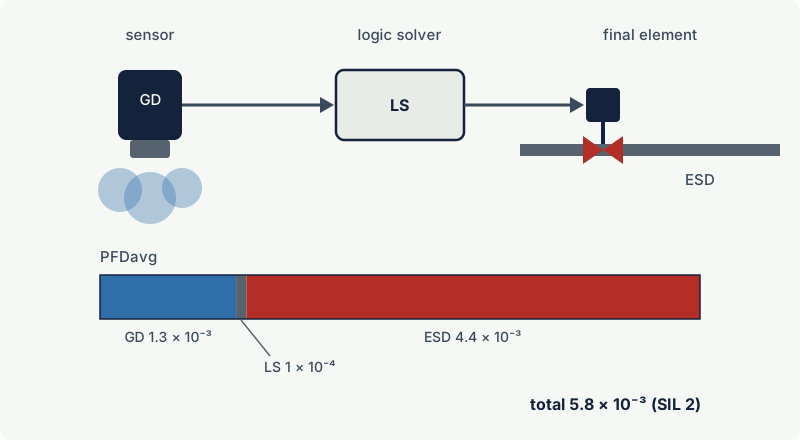
A safety instrumented function is one specific protective action: for example, "on detection of flammable gas at 40 %LEL by two of three detectors at compressor K-101, close the inlet ESD (emergency shutdown) valve and stop the compressor". It has three subsystems:
- Sensors: the gas detectors (point, open path or sampling).
- Logic solver: a safety controller or trip amplifier that compares signals with set points and applies the voting.
- Final elements: valves, motor starters, fans, dampers, power isolation.
Alarms that only inform an operator are not SIFs in this sense; an operator response can be credited as a separate protection layer only under the conditions IEC 61511 sets for it.
Demand mode, PFDavg and SIL
Most gas detection SIFs act rarely: a dangerous release is, one hopes, an unusual event. IEC 61508:2010 and IEC 61511 define low demand mode as demands no more often than once a year (the first edition of IEC 61508 also tied it to twice the proof test frequency; the 2010 edition dropped that condition). Its measure is the average probability of failure on demand (PFDavg): the fraction of time the function would fail to act if asked to. Functions with more frequent demands are measured by the probability of a dangerous failure per hour (PFH).
| SIL | PFDavg (low demand) | Risk reduction factor | PFH (high demand or continuous), per hour |
|---|---|---|---|
| SIL 1 | 10⁻² to < 10⁻¹ | 10 to 100 | 10⁻⁶ to < 10⁻⁵ |
| SIL 2 | 10⁻³ to < 10⁻² | 100 to 1,000 | 10⁻⁷ to < 10⁻⁶ |
| SIL 3 | 10⁻⁴ to < 10⁻³ | 1,000 to 10,000 | 10⁻⁸ to < 10⁻⁷ |
| SIL 4 | 10⁻⁵ to < 10⁻⁴ | 10,000 to 100,000 | 10⁻⁹ to < 10⁻⁸ |
The required SIL comes from a hazard and risk assessment (for example a layer of protection analysis or risk graph, as described in IEC 61511-3), not from the detector datasheet.
The three requirements
A SIF achieves a SIL only if all three of the following are met; the lowest one sets the achieved SIL:
- Random hardware failures: the calculated PFDavg (or PFH) of the whole function is inside the band.
- Architectural constraints: each subsystem has enough hardware fault tolerance (HFT). An HFT of N means N+1 faults are needed to lose the function: a single detector has HFT 0, a 1oo2 or 2oo3 arrangement has HFT 1.
- Systematic capability: every device was designed and built under a process good enough for the SIL (systematic capability SC 1 to SC 4 under IEC 61508), or is justified by documented prior use under IEC 61511, and the application software and installation follow the lifecycle.
IEC 61511-1:2016 sets the minimum HFT as follows; the standard also describes conditions under which other approaches are acceptable, so check the text for a real project:
| SIL | Minimum HFT |
|---|---|
| SIL 1 | 0 |
| SIL 2, low demand | 0 |
| SIL 2, high or continuous demand | 1 |
| SIL 3 | 1 |
| SIL 4 | 2 |
Failure modes of gas detectors
Functional safety analysis sorts failures into safe (the function trips when it should not) and dangerous (the function would not trip when it should), and each into detected (by diagnostics) or undetected. Only dangerous undetected failures, with rate λDU, remain hidden until a proof test or a real demand.
For gas detectors, the important point is which failures the instrument can see itself:
| Failure | Typical detection | Category |
|---|---|---|
| Broken sensor wire, failed lamp or source, electronics fault, loss of power | Self-diagnostics; output goes to a fault current or fault state | Dangerous detected (if the logic treats the fault correctly) |
| Catalytic bead poisoned or inhibited | Not detected; zero is still stable | Dangerous undetected |
| Sinter or weather guard blocked by paint, dust or ice | Usually not detected | Dangerous undetected |
| Electrochemical cell dried out or exhausted | Often not detected by the instrument | Dangerous undetected |
| Detector calibrated for the wrong gas, or alarm set point wrong | Not detected | Systematic failure |
| Open path beam blocked | Detected as beam block | Dangerous detected |
This is why IEC guidance stresses that errors and failures of gas detectors may not be self-evident (see gas detector calibration and bump testing). It also shows that a detected fault only helps if the logic solver acts on it: the safety requirement specification must say whether a faulty detector counts as tripped, as healthy, or reduces the voting, and what the operators must do.
Voting
Voting combines several detectors in one function. The notation MooN means M out of N detectors must see gas to trip.
| Voting | Trips on | Dangerous failure tolerated | Spurious trip from one faulty detector | Typical use |
|---|---|---|---|---|
| 1oo1 | One detector | None (HFT 0) | Yes | Alarms, simple functions |
| 1oo2 | Either of two | One (HFT 1) | Yes, more likely than 1oo1 | Where missing a release is unacceptable and spurious trips are tolerable |
| 2oo2 | Both of two | None | No | Avoid for safety: one dead detector disables the function |
| 2oo3 | Any two of three | One (HFT 1) | No | Executive actions such as ESD and power isolation |
Redundancy brings its own limit: common cause failures. Detectors of the same type, calibrated with the same gas by the same technician, exposed to the same silicone vapour, can all lose sensitivity together. Calculations include a common cause factor (β) for this, and in practice it often dominates the redundant subsystem.
For gas detection there is a second limit that reliability calculations do not show: the gas must reach the voted detectors. Three detectors spread over a large module may never see the same small cloud at the same time. A 2oo3 function on such a layout is reliable on paper and blind in practice. Detector placement (see where to install gas detectors) and, for larger plants, fire and gas mapping are part of the safety design.
A common arrangement is to raise an alarm on any single detector (1ooN) and start executive actions on 2ooN, so people are warned early while plant trips need confirmation. See fixed gas detection systems.
Proof testing
Dangerous undetected failures accumulate between tests. A proof test is a periodic test designed to reveal them so they can be repaired. The UK HSE notes that PFD calculations assume the test reveals all such failures at the specified interval and that repairs happen within the assumed time, and that in practice such testing sometimes does not reveal all of the undetected failure modes.
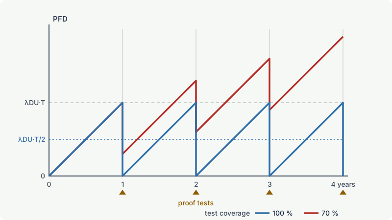
For a single device with a perfect proof test every T hours, the simplified textbook result is:
PFDavg ≈ λDU x T / 2
The interval T used in this calculation is a maximum test interval for the plant. It must be written into the maintenance system, not left in the SIL report.
What a good gas detector proof test includes
- Gas at the sensor. Apply certified test gas through the manufacturer's adapter and confirm the reading and the trip. Simulating the signal by injecting current into the loop tests the wiring and logic solver but proves nothing about the sensor; it has a low proof test coverage for the detector.
- The whole loop. From the sensor through the logic solver to the final element: the valve must actually close (or the fan start, or the breaker open), within the required time.
- As-found data first. Record the reading and response before any adjustment. A detector that needed recalibration was, during part of the interval, a failure; trend these results to validate the λDU assumed in the calculation.
- Bypasses and inhibits. The function is unavailable while inhibited. Control, log and remove inhibits; arrange compensating measures during the test.
Calibration practice for fixed detectors is covered in gas detector calibration and bump testing.
Worked example: where the SIL comes from
A compressor area needs a SIF to close the gas inlet valve on detection of flammable gas. The risk assessment requires SIL 2 (PFDavg below 10⁻², risk reduction above 100). The failure data below are illustrative only; real values come from the device certificates or recognised data sources.
| Subsystem | Assumed λDU per hour | Test interval | PFDavg ≈ λDU·T/2 |
|---|---|---|---|
| One infrared gas detector (1oo1) | 3 x 10⁻⁷ | 1 year (8,760 h) | 1.3 x 10⁻³ |
| Safety logic solver (from its certificate) | not applicable | 1 year | 1.0 x 10⁻⁴ |
| ESD valve with actuator and solenoid | 2 x 10⁻⁶ | 1 year | 8.8 x 10⁻³ |
| Total | 1.02 x 10⁻² |
Step 1. The total is just above 10⁻², so the function reaches only SIL 1, although the detector certificate says "SIL 2" and the logic solver "SIL 3". The valve contributes about 86 % of the failure probability.
Step 2. Testing the valve every six months halves its contribution to 4.4 x 10⁻³. The total becomes 5.8 x 10⁻³, inside the SIL 2 band (risk reduction about 170).
Step 3. Using three detectors voted 2oo3 instead of one, with a common cause factor of 5 %, the simplified equations (ignoring diagnostics and repair time) give a detector subsystem PFDavg of about (λDU·T)² + β·λDU·T/2 ≈ 7 x 10⁻⁵, almost all of it from common cause. The total falls to about 4.6 x 10⁻³. The bigger benefits of 2oo3 here are fewer spurious trips and tolerance of one failed detector, provided the layout lets a credible cloud reach two of them.
Finally, the architectural and systematic requirements must also be checked: HFT 0 is acceptable for SIL 2 in low demand mode under IEC 61511-1:2016, and every device needs systematic capability of at least SC 2 or a prior use justification.
How to read a detector's SIL certificate
A detector "SIL certificate" is usually issued by an assessment body after an IEC 61508 assessment. It typically states:
- The SIL capability for a single device (HFT 0) and sometimes for redundant use, for example "SIL 2 capable, SIL 3 in redundant configuration".
- Systematic capability (SC 1 to SC 4 in IEC 61508): the quality of the design and development process.
- Hardware type and safe failure fraction (SFF). Detectors with microprocessors are normally classed as complex (Type B) devices under IEC 61508; the SFF is the proportion of failures that are safe or detected.
- Failure rates: λSD, λSU, λDD, λDU, or a PFDavg for a stated proof test interval.
- Conditions: the firmware version, the outputs that are part of the safety function (often the 4 to 20 mA output, not every relay or digital interface), the configuration, the proof test procedure and interval, and the environment. These are set out in the safety manual, which is part of the certificate.
What the certificate does not say:
- It does not make your function SIL 2. That depends on your architecture, logic solver, final elements, test intervals and calculation.
- It does not cover measuring performance (accuracy, response time, cross-sensitivity). That is the role of performance testing to IEC 60079-29-0 (formerly IEC 60079-29-1).
- It does not cover explosion protection. The Ex certificate is a third, separate document (see ATEX vs IECEx).
- It does not cover detector location. A perfectly reliable detector in the wrong place detects nothing.
Fire and gas systems and detector coverage
Many offshore and onshore fire and gas (F&G) systems do not fit the classical SIF model well. They mitigate the consequences of a release rather than preventing it, and no layout detects every possible release. ISA-TR84.00.07 addresses this by adding detector coverage (geographic coverage, or scenario coverage weighted by release location, frequency and size) to safety availability (the reliability side, calculated much as above). A gas detection function with excellent PFDavg but 60 % scenario coverage is not a high-integrity function. Coverage targets and mapping methods are a design decision for the project, and they belong in the safety requirement specification alongside the SIL.
Common mistakes
- Buying a "SIL 2 detector" and calling the system SIL 2. The SIL belongs to the function. Calculate the whole loop, including the final elements.
- Proof testing with current injection only. It never reveals a poisoned or blocked sensor. Apply gas at the sensor.
- Ignoring the safety manual. Using an uncertified output, a different firmware version or a longer test interval than the certificate assumes invalidates the failure data.
- Voting detectors that the gas cannot reach together. 2oo3 over a large area reduces spurious trips and can also make the function blind to small clouds. Check placement against credible releases.
- Leaving fault handling undefined. A detector in fault must lead to a defined action (trip, degraded voting, alarm and compensating measures), written in the safety requirement specification.
- Forgetting systematic failures. Wrong calibration gas, wrong set point or a wrong gas group in the Ex marking are not covered by λ values. They are prevented by the safety lifecycle: specification, verification, validation and management of change.
Frequently asked questions
Can a gas detector be SIL 2?
Strictly, no: SIL is a property of a complete safety instrumented function. A detector can be certified as suitable (or "capable") for use in functions up to SIL 2 under IEC 61508. Whether the function reaches SIL 2 depends on the whole loop, including the logic solver, final elements, voting and proof test intervals.
What SIL do gas detection systems normally need?
There is no default. The required SIL comes from a hazard and risk assessment of each function, for example a layer of protection analysis under IEC 61511, and it depends on the consequences and on the other protection layers. A SIL 3 requirement calls for fault tolerant architectures (HFT 1 under IEC 61511-1:2016) and short, thorough proof tests, so it is demanding to achieve with gas detection.
How often should gas detectors in a SIF be proof tested?
At least as often as the proof test interval used in the PFD calculation, and never less often than the manufacturer, the safety manual or regulations require. The test should apply gas to the sensor and prove the whole loop to the final element, because the dominant dangerous failures of gas sensors are not revealed by diagnostics.
What is the difference between 1oo2 and 2oo3 voting for gas detectors?
1oo2 trips when either of two detectors sees gas: it tolerates one dangerous failure but trips spuriously if either detector fails high. 2oo3 trips when any two of three see gas: it tolerates one dangerous failure and one spurious signal, so it is common for executive actions. Both rely on the gas cloud reaching the voted detectors.
Which standard covers functional safety of gas detection systems?
IEC 61511 for process industry safety instrumented systems, built on the basic standard IEC 61508. IEC 60079-29-3 gives guidance specific to fixed gas detection systems, and ISA-TR84.00.07 covers performance-based fire and gas system design, including detector coverage.
Related on excodex
- Fixed gas detection systems: design principles and when they are required
- Gas detector calibration and bump testing
- Where to install gas detectors: height, distance and common mistakes
- Open path gas detectors: line-of-sight detection for large areas
- Setting gas detector alarm levels for flammable and toxic gases
- Standards spaces IEC 61511, IEC 60079-29-0 and IEC 60079-29-2; questions in the forum
Standards and further reading
- IEC 61508-1:2010, Functional safety of electrical, electronic and programmable electronic safety-related systems, part 1: general requirements (edition 2.0; parts 2 to 7 cover hardware, software, definitions and guidance): https://webstore.iec.ch/en/publication/5515
- IEC 61511 series, Functional safety: safety instrumented systems for the process industry sector (IEC 61511-1:2016 with amendment 1:2017, IEC 61511-2:2016, IEC 61511-3:2016): https://webstore.iec.ch/en/publication/5527
- IEC 60079-29-3:2014, Explosive atmospheres, gas detectors: guidance on functional safety of fixed gas detection systems: https://webstore.iec.ch/publication/645
- IEC 60079-29-0:2025, Explosive atmospheres, gas detection equipment: general requirements and test methods: https://webstore.iec.ch/en/publication/77173
- ISA-TR84.00.07, Guidance on the evaluation of fire, combustible gas and toxic gas system effectiveness (current version 2026).
- UK HSE, operational guidance on proof testing of safety instrumented systems in the onshore chemical and specialist industry: https://hse.gov.uk/foi/internalops/og/og-00054.htm
This article is general technical information prepared by the excodex editorial team. It does not replace the applicable standards, the equipment certificates and instructions, national regulations or the assessment of a competent person.