Open path gas detectors: line-of-sight detection for large areas
Abstract
An open path gas detector sends an infrared beam across up to hundreds of metres and measures the gas along the whole line in LEL·m. How it works, what LEL·m means, where beams are used, alignment, limits and how to combine them with point detectors.
An open path gas detector (also called a line-of-sight or beam detector) sends a beam of infrared light from a transmitter to a receiver, or to a reflector and back, and measures how much of it is absorbed by flammable gas anywhere along the line. Because it adds up all the gas on the beam, it reports an integral concentration in LEL·m (lower explosive limit times metres, written LFL·m in IEC documents), not a concentration at a point. One beam can cover a path from a few metres to well over a hundred metres, which makes open path detection the practical choice for perimeters, open process areas and offshore modules, where point detectors would need a dense grid to catch a drifting cloud.
This article explains the measuring principle, what an LEL·m reading does and does not tell you, typical applications and alarm levels, alignment and installation, the limitations, and how open path and point detectors are combined into one system.
Key points
- An open path detector measures the sum of gas concentration over the beam length. 1 LEL·m equals 1 m of gas at 100 %LEL, or 5 m at 20 %LEL, or 10 m at 10 %LEL: the detector cannot tell these apart.
- The IEC performance standard for open path equipment described paths ranging typically from one metre to a few kilometres; that standard (IEC 60079-29-4) has been replaced since November 2025 by IEC 60079-29-0, which covers open path flammable (FL-OP) and toxic (TX-OP) detectors.
- Indicative alarm levels in a UK HSE research report on offshore detection are 1 LFL·m for the first alarm and 2 LFL·m for the second, adjusted for confinement and the hydrocarbons present.
- Open path detectors use infrared absorption by carbon-hydrogen bonds, so like infrared point detectors they cannot detect hydrogen.
- A blocked beam (a person, a vehicle, heavy fog, a lifted load) gives a fault or beam-block warning, not a gas reading: during that time the line is unprotected.
- HSE notes that poorly engineered supports and unsuitable sites cause the vast majority of open path problems. Rigid mounting and a clear line of sight are design requirements, not details.
- Open path and point detectors do different jobs. The usual design puts beams along boundaries and across open areas and point detectors at likely leak sources, in enclosures and at low points for heavy gases.
How an open path detector measures gas
Infrared absorption over a path
Most flammable gases and vapours are hydrocarbons. Their carbon-hydrogen (C-H) bonds absorb infrared light at characteristic wavelengths, both in the mid infrared around 3.3 to 3.5 µm used by most point infrared sensors and in weaker overtone bands in the near infrared. The HSE research report on offshore gas detection notes that many open path detectors measure absorption at about 2.3 µm. The physics is the same as in an infrared point detector (see catalytic vs infrared detectors); the difference is that the optical path is the open air between two housings instead of a few centimetres inside a sensor.
The receiver compares at least two wavelengths:
- A measuring wavelength that hydrocarbons absorb.
- One or more reference wavelengths close to it that hydrocarbons do not absorb.
Fog, rain, dirt on the windows and slow changes in the lamp reduce both signals by about the same amount, so their ratio stays constant. Only gas on the beam reduces the measuring signal more than the reference. The HSE report notes that the newest models use two or three reference wavelengths, and that the reference channel also allows the detector to recognise a blocked beam.
Absorption follows the Beer-Lambert law: what matters is the number of absorbing molecules the light passes, which is concentration multiplied by the length of gas it crosses. A thin rich cloud and a long dilute cloud can absorb the same amount of light.
What LEL·m means
The output is therefore a path-integrated concentration: the concentration at each point along the beam, in %LEL, added up over the beam length in metres, then divided by 100. The unit is LEL·m (or LFL·m). A uniform cloud gives:
reading (LEL·m) = cloud width on the beam (m) x average concentration in the cloud (%LEL) / 100
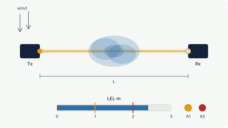
Dividing the reading by the beam length gives the path-average concentration in %LEL. Some detectors can be configured to display this, but on a long path it is misleading. The HSE report recommends %LFL (path-average) units only for paths up to about 5 m, LFL·m units for longer paths, and warns that averaging over long paths can miss significant clouds. It gives the example of a 64 m³ cloud of 10 % vol methane (227 %LFL on a lower limit of 4.4 % vol), which is large enough to accelerate a flame, yet on a 40 m beam it would produce only half the path-average reading it gives on a 20 m beam.
Worked example: three clouds, one reading
A 20 m beam crosses an open process area. Three different methane clouds drift onto it (methane LEL 4.4 % vol):
| Cloud | Width on the beam | Average concentration | Reading | Path average over 20 m |
|---|---|---|---|---|
| A: compact cloud | 4 m | 50 %LEL (2.2 % vol) | 2 LEL·m | 10 %LEL |
| B: wide, dilute cloud | 20 m | 10 %LEL (0.44 % vol) | 2 LEL·m | 10 %LEL |
| C: small rich pocket | 1 m | 200 %LEL (8.8 % vol) | 2 LEL·m | 10 %LEL |
All three give 2 LEL·m, which would reach a typical second alarm. But they are very different hazards: cloud B is far below the flammable range everywhere, cloud A is a sizeable volume at half the LEL, and cloud C is a pocket inside the flammable range of methane (4.4 to 17 % vol). A path-average display would show "10 %LEL" for all three and understate A and C badly.
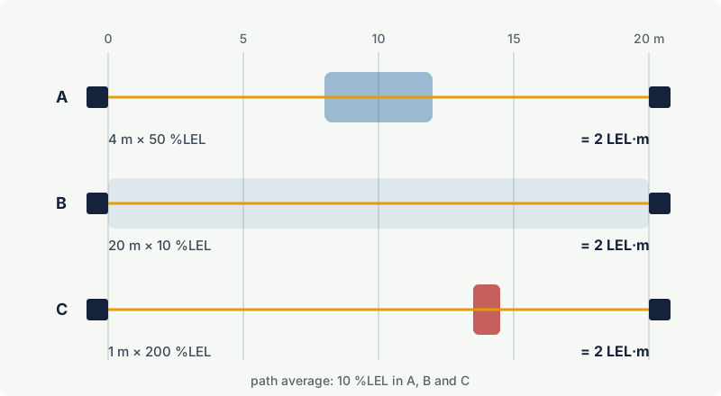
Open path detectors are not imprecise; they measure exactly what they claim to measure. But alarm levels must be set in LEL·m with a target cloud in mind, and the reading must never be taken as a point concentration.
Where open path detectors are used
The strength of a beam is that a cloud has to cross a line, not hit a point. HSE describes open path detectors as the only practical option for boundary monitoring and notes that in open areas they have a higher probability of detecting a release than point detectors, because they rely less on the gas moving to a particular spot.
| Application | Purpose of the beam | Notes |
|---|---|---|
| Perimeter of a process area or tank farm | Detect gas leaving the area towards people, roads or neighbours | Several beams in series along the fence line |
| Offshore modules and open decks | Detect a cloud in a well-ventilated module before it reaches ignition sources | HSE reports typical offshore ranges of up to 30 m, depending on conditions |
| Between process area and occupied buildings or air intakes | Warn before gas reaches a control room, HVAC (heating, ventilation and air conditioning) inlet or muster point | Combine with detectors at the intake itself |
| Along pipe racks, loading bays, jetties | Long linear hazards where a point grid would need many detectors | Check beam height against gas density |
| Toxic gas at fence lines and production areas | Open path detectors for toxic gases such as hydrogen sulphide, using a laser or flash lamp source and a ppm·m reading | IEC 60079-29-0 includes an open path toxic type (TX-OP) |
Open path detection is a complement, not a substitute. It does not remove the need for area classification or for Ex equipment, and both the transmitter and receiver installed in a hazardous area must themselves be certified for the zone, gas group and temperature class.
Alarm levels in LEL·m
There is no universal set point, and the right value depends on the beam length, the target cloud and the action the alarm triggers. The HSE research report gives indicative levels for offshore use:
| Detector type | First alarm | Second alarm | Comment |
|---|---|---|---|
| Point detector | 10 to 20 %LFL | 25 to 40 %LFL | Depends on confinement and hydrocarbons |
| Open path detector | 1 LFL·m | 2 LFL·m | Depends on confinement and hydrocarbons |
A useful way to check an LEL·m set point is to ask which clouds it will catch. At 1 LEL·m the first alarm is reached by a 5 m wide cloud at 20 %LEL, or a 10 m cloud at 10 %LEL. The HSE report bases its detection targets on a stoichiometric cloud about 6 m long, a size linked to damaging overpressure; a 6 m cloud at only 20 %LEL already gives 1.2 LEL·m. For very short paths the HSE report allows the detector to be treated as a point detector scaled in %LEL (it gives about 5 to 6 m as the limit).
As with any infrared detector, the response depends on the gas. A beam calibrated for methane will read propane, ethylene or solvent vapours differently, so the calibration gas and the alarm levels must match the gases actually expected. See setting gas detector alarm levels.
Alignment, installation and testing
Two designs
The IEC performance standard distinguished two arrangements:
- Transmitter and receiver at opposite ends of the path (a "two-ended" or bistatic system). HSE notes that offshore installations mainly use this type, for stability.
- Transceiver and reflector, where one housing sends and receives the beam and a retroreflector, or even a topographic feature, returns it. Only one end needs power and cabling, but the light crosses the gas twice.
Alignment
An open path detector only works if the beam lands on the receiver. During commissioning the two units are aligned with a telescope or an alignment tool and the received signal strength is recorded. After that, anything that moves the mounting moves the beam:
- Rigid supports. Structures flex in wind and with temperature; offshore decks move. HSE notes that poorly engineered supports and unsuitable sites account for the vast majority of problems, and that keeping the working range fairly short reduces misalignment from flexing supports.
- Clear line of sight. HSE notes that a minimum clear radius around the beam, typically about 0.5 m, is needed to avoid signal disturbance from obstacles. Check for future obstructions: scaffolding, stacked materials, parked vehicles, vegetation.
- Mounting height. HSE notes that offshore beams are typically mounted around 3 m above the deck where practical, to reduce interruptions by people and to ease maintenance. The height must still suit the gas: a beam above a heavy vapour cloud that hugs the ground will not see it.
- Sunlight and hot sources. HSE lists blinding by sunlight, fires, hot (black body) sources and lamps among the failure modes. Avoid aiming the receiver into the rising or setting sun or towards flares.
Testing
Open path detectors are normally calibrated in the factory. In the field they are function tested with test filters, gas cells or plastic test sheets placed in the beam, which simulate a known LEL·m. HSE describes these as function check devices only, not as absolute calibration, and points out that the response to a sheet depends on how the detector is configured: a 1 LFL·m sheet reads about 20 % of full scale on a 0 to 5 LFL·m range. Record the received signal level at each visit; a slow fall shows dirty windows or drifting alignment before it becomes a fault. General calibration and testing practice is covered in gas detector calibration and bump testing.
Limitations
- No location, no peak concentration. The detector tells you that gas is on the line and how much, not where along the line or how concentrated.
- Beam block means blind. People, vehicles, cranes, heavy fog, snow, heavy rain and dense steam can block the beam. The detector reports a fault or beam-block condition after a set time, but it cannot detect gas while blocked. HSE notes that high levels of steam impair performance.
- No hydrogen. Hydrogen has no infrared absorption in the bands used, so hydrogen needs point detectors of another type (catalytic, thermal conductivity, electrochemical) or acoustic leak detection. See hydrogen safety basics.
- Gas-dependent response. Mixtures and unexpected substances are read with an error that may be large.
- Harder maintenance. Two housings, often at height and far apart, both need cleaning and inspection.
- Location rules still apply. Gas density, wind, congestion and release locations decide where the line should be, exactly as for point detectors (see where to install gas detectors).
Combining open path and point detectors
Point and open path detectors answer different questions. A point detector says "the concentration here is X %LEL"; a beam says "there is Y LEL·m of gas somewhere on this line". A good layout uses each for what it does well:
| Detector | Best placed | Why |
|---|---|---|
| Point detector | Close to likely leak sources (pump seals, compressor packing, flanges), in enclosures and buildings, at low points for heavy gases, at air intakes | Responds to local concentration; works in confined spaces; catches gas where it accumulates |
| Open path beam | Boundaries, open and well-ventilated areas, long linear hazards, between hazard and receptor | Catches a drifting cloud wherever it crosses the line |
| Acoustic leak detector | High-pressure equipment in open, windy areas | Hears the leak itself, independent of where the gas goes |
The HSE report points out that point detectors suit open areas where heavy gas or liquids are likely to be released, and heavier hydrocarbons in closed areas, while open path detectors are generally better in open areas, and that a mix of detector types (point, open path and acoustic) gives more resilient coverage than any single type.
When detectors trigger executive actions, voting rules (for example 2 out of N detectors) reduce spurious trips. Some designs vote beams with point detectors. Whatever scheme is chosen, a credible cloud must be able to reach both voted detectors; otherwise the voting makes the system less safe. Voting and integrity are discussed in fixed gas detection systems and gas detection and functional safety.
Example: An onshore gas compressor station has an open compressor area next to an office building. A practical layout puts point infrared detectors near each compressor's packing and seals, a second set at the inlet of the office ventilation system, and two open path beams along the side of the compressor area facing the office. The point detectors find small leaks early at the source. The beams catch a cloud from any source drifting towards the office, including from equipment between point detectors. A beam-block fault during maintenance is reported to the control room, which knows that the point detectors near the office intake are still active.
Common mistakes
- Reading LEL·m as %LEL. 2 LEL·m is not 2 %LEL. It is the total gas on the beam and can come from a flammable pocket or from a harmless dilute haze.
- Path averaging on long beams. Displaying the path-average concentration on a 50 m beam hides compact, dangerous clouds. Use LEL·m units and alarm levels based on a target cloud size.
- Mounting on flexible structures. Handrails, light poles and thin brackets move with wind and temperature. Mount on rigid steelwork and recheck alignment after nearby construction.
- Expecting a beam to detect hydrogen. Infrared open path detectors do not see hydrogen. Use another technology.
- Treating beam-block as a minor fault. While blocked, the line is not monitored. Define what the operators must do (for example, portable monitoring or stopping work) when a beam has been blocked for longer than a set time.
- Replacing all point detectors with beams. Beams do not cover enclosures, pits or accumulation points well and do not give a local concentration for entry decisions.
Frequently asked questions
What does LEL·m mean on a gas detector?
LEL·m (or LFL·m) is the unit of an open path detector's reading. It is the gas concentration in %LEL integrated along the beam, divided by 100: 1 LEL·m equals 1 m of gas at 100 %LEL or 10 m at 10 %LEL. It tells you how much flammable gas is on the line of sight, not the concentration at any one point.
How far can an open path gas detector see?
The IEC performance standard for open path equipment described paths ranging typically from one metre to a few kilometres, and individual products are rated for specific minimum and maximum distances. In practice the usable range is set by alignment stability and visibility; a UK HSE report gives typical offshore ranges of up to about 30 m. Shorter, rigidly mounted beams are more reliable.
What alarm levels are used for open path detectors?
There is no single mandatory value. A UK HSE research report on offshore installations gives indicative levels of 1 LFL·m for the first alarm and 2 LFL·m for the second, depending on confinement and the hydrocarbons present. Check the chosen levels against the size and concentration of the cloud you need to detect.
Can an open path detector detect hydrogen?
No. Open path detectors for flammable gas rely on infrared absorption by carbon-hydrogen bonds, and hydrogen does not absorb at those wavelengths. Hydrogen needs catalytic, thermal conductivity or electrochemical point detectors, or acoustic leak detection.
Does fog or rain cause false alarms on open path detectors?
Fog, rain and dirt reduce the measuring and reference wavelengths by about the same amount, so the detector compensates for them and they should not produce a gas reading. Heavy fog, snow or dense steam can, however, reduce the signal so much that the detector reports a beam-block or low-signal fault, during which it cannot detect gas.
Should I use open path or point gas detectors?
Usually both. Open path beams are best for perimeters, open areas and long linear hazards where a cloud must cross a line; point detectors are best near leak sources, in enclosures and at low points where gas accumulates. A combination, sometimes with acoustic leak detectors, gives the most reliable coverage.
Related on excodex
- Fixed gas detection systems: design principles and when they are required
- Catalytic (pellistor) vs infrared flammable gas detectors
- Where to install gas detectors: height, distance and common mistakes
- Setting gas detector alarm levels for flammable and toxic gases
- LEL and UEL explained
- Gas library: /gas, methane, propane; standards spaces IEC 60079-29-0 and IEC 60079-29-2; questions in the forum
Standards and further reading
- IEC 60079-29-0:2025, Explosive atmospheres, gas detection equipment: general requirements and test methods, including open path flammable (FL-OP) and toxic (TX-OP) types; it replaces IEC 60079-29-1 and IEC 60079-29-4: https://webstore.iec.ch/en/publication/77173
- IEC 60079-29-4:2009 (withdrawn, replaced by IEC 60079-29-0), performance requirements of open path detectors for flammable gases: https://webstore.iec.ch/publication/647
- IEC 60079-29-2:2015, Explosive atmospheres, gas detectors: selection, installation, use and maintenance of detectors for flammable gases and oxygen; the second edition added open path detection and an annex on atmospheric visibility.
- UK HSE Research Report RR1123, Fixed flammable gas detector systems on offshore installations: optimisation and assessment of effectiveness (2017): https://www.hse.gov.uk/research/rrpdf/rr1123.pdf
This article is general technical information prepared by the excodex editorial team. It does not replace the applicable standards, the equipment certificates and instructions, national regulations or the assessment of a competent person.