Catalytic (pellistor) vs infrared flammable gas detectors
Abstract
Catalytic sensors burn gas on a heated bead and detect almost every flammable gas, including hydrogen, but need oxygen and can be poisoned. Infrared sensors measure light absorption, cannot be poisoned, but cannot see hydrogen. How each works and how to choose.
Catalytic (pellistor) and infrared (IR) sensors are the two main technologies for detecting flammable gas in the 0 to 100 %LEL range. A catalytic sensor burns the gas on a heated catalyst bead and measures the heat released, so it responds to almost every flammable gas and vapour, including hydrogen, but it needs oxygen, can be poisoned without warning and can read falsely low above the LEL. An infrared sensor measures how much infrared light the gas absorbs at a wavelength typical of hydrocarbons; it cannot be poisoned and works without oxygen, but it cannot detect hydrogen or other gases that do not absorb at its wavelength.
This article explains how both sensors work, what goes wrong with each, how their response differs from gas to gas, and how to choose between them.
Key points
- A catalytic sensor is a pair of heated beads in a bridge circuit: gas burns on the active bead and raises its temperature and resistance; the inert reference bead compensates for ambient changes.
- Catalytic sensors need oxygen to work; IEC guidance and a US OSHA hazard bulletin both put the practical minimum at about 10 % vol oxygen.
- Silicones, lead compounds, sulphur compounds and organophosphorus compounds can poison a catalytic sensor permanently, and the loss of sensitivity is not shown as a fault; only a gas test reveals it.
- Infrared flammable gas sensors measure absorption by carbon-hydrogen bonds around 3.3 to 3.5 µm. Hydrogen has no infrared absorption, so IR sensors cannot detect hydrogen.
- Above the LEL, a catalytic sensor's signal can fall back into the normal range; a latching over-range function is essential.
- Both technologies respond differently to different gases. A detector calibrated for one gas reads another gas correctly only after the relative response is taken into account.
- IR sensors usually reveal their own failures (dirty or blocked optics trigger a fault), which makes them attractive for safety instrumented functions; catalytic sensors need more frequent gas testing.
How a catalytic (pellistor) sensor works
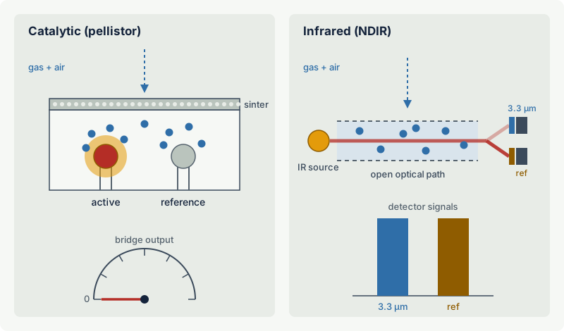
A pellistor sensor contains two small ceramic beads, each moulded around a fine platinum wire coil:
- The active (detector) bead is coated with a noble metal catalyst.
- The reference (compensator) bead is built the same way but is inactive, so flammable gas does not burn on it.
Both coils are heated electrically to around 500 °C and connected in a Wheatstone bridge. When flammable gas reaches the beads, it oxidises on the catalyst of the active bead, even at concentrations far below the LEL. The reaction heat raises the temperature of that bead, the resistance of its platinum coil rises, and the bridge goes out of balance. Below the LEL, the output is close to proportional to the gas concentration. The reference bead sees the same ambient temperature, humidity and pressure changes and cancels them out.
The beads sit behind a sintered metal disc or similar flame arrester. Because the beads are hot enough to ignite the gas they measure, the sensor head is normally a flameproof (Ex d) design: the sinter lets gas diffuse in but stops a flame from travelling out.
What a catalytic sensor needs
A catalytic sensor measures combustion, so the conditions for combustion must be present:
- Oxygen. Without enough oxygen the gas cannot burn on the bead. IEC guidance on gas detector selection gives a minimum of about 10 % vol oxygen, and a 1990 OSHA hazard information bulletin, written after a welder was killed when a nitrogen-purged tank exploded, warned that combustible gas indicators do not indicate correctly below 10 % oxygen. US Bureau of Mines work on mine-fire atmospheres showed catalytic methanometers reading low when oxygen was insufficient for complete combustion.
- Gas access. The gas must diffuse through the sinter. Large, heavy molecules diffuse more slowly and give a lower, slower response than light ones. Blocked sinters (dust, paint, ice, insects) reduce the signal.
Above the LEL: the fold-back problem
As the concentration rises above the LEL, the bead consumes oxygen faster than it can be replaced. Beyond a maximum somewhere in the flammable range, the signal falls again, and in pure gas it is zero. A catalytic sensor in a very rich atmosphere can therefore show a reading that looks normal, or even zero.
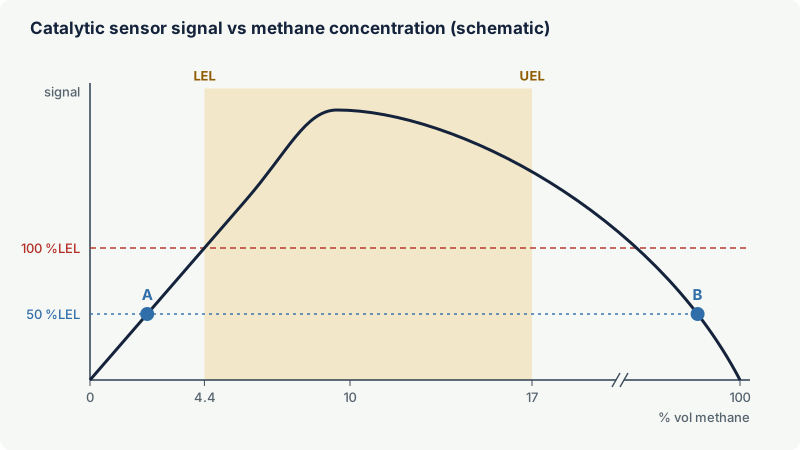
The standard defence is a latching over-range function: once the reading exceeds full scale, the detector and the control system hold an over-range alarm until a person resets it after confirming the atmosphere. IEC guidance notes that instruments meeting the IEC performance standard should have this function, but that stand-alone transmitters and older instruments may not. The same guidance warns that exposure far above the measuring range can leave a catalytic sensor with a shifted zero or reduced sensitivity, sometimes for hours, sometimes permanently.
Poisons and inhibitors
The catalyst is the weak point. Some substances destroy its activity permanently (poisons); others suppress it temporarily (inhibitors). IEC guidance lists, among others:
| Type | Examples | Typical sources |
|---|---|---|
| Poisons (usually permanent) | Silicones | Sealants, greases, release agents, some cosmetics and cleaners |
| Poisons | Tetraethyl lead and other organic lead | Leaded fuels, aviation gasoline |
| Poisons | Organophosphorus compounds | Phosphate ester fire-resistant hydraulic fluids, some pesticides |
| Poisons or inhibitors | Sulphur compounds, including hydrogen sulfide and sulphur dioxide | Sour gas, refinery streams, sewage, biogas |
| Inhibitors (often temporary) | Halogenated compounds | Refrigerants, chlorinated solvents, fire suppression agents |
Poisoning is dangerous because it is not self-revealing. The bridge still balances in clean air, the zero reading looks perfect and no fault is reported, but the sensor no longer responds properly to gas. "Poison-resistant" sensor versions and filters reduce the problem but do not remove it, and filters can slow or reduce the response to heavier hydrocarbons. Where poisons may be present, frequent bump tests with gas are the only reliable check (see gas detector calibration and bump testing).
How an infrared (NDIR) sensor works
Most flammable gases and vapours are hydrocarbons or organic compounds, and their carbon-hydrogen bonds absorb infrared light in a band around 3.3 to 3.5 µm (methane absorbs strongly near 3.3 µm). A non-dispersive infrared (NDIR) sensor uses this:
- An infrared source shines through an optical path that is open to the surrounding atmosphere, usually protected by a weather guard or mesh.
- At the end of the path, two detectors with optical filters measure the light: one at the absorption wavelength of the target gas (measuring channel), one at a nearby wavelength that hydrocarbons do not absorb (reference channel).
- When gas enters the path, the measuring signal falls and the reference signal does not. The ratio of the two gives the gas concentration.
The ratio method compensates for lamp ageing, dust on the windows and other effects that reduce both signals equally. Absorption follows the Beer-Lambert law, which is not linear, so the electronics linearise the output to %LEL or % vol.
What an IR sensor does well
- No poisoning. There is no catalyst, so silicones, lead, sulphur and halogenated compounds do not destroy the sensitivity.
- No oxygen needed. IR works in inert atmospheres, in nitrogen-purged equipment and in oxygen-deficient spaces.
- No fold-back. Absorption keeps increasing with concentration, so a rich atmosphere is not mistaken for a lean one. IR instruments can be ranged in % vol up to 100 % for purging and inerting work.
- Self-revealing faults. A blocked beam, failed lamp or heavily contaminated optics changes the reference signal too, and the detector reports a fault rather than a false zero.
- No consumption of the sensing element by gas exposure, so high concentrations do not damage it.
What an IR sensor cannot do
- It cannot detect hydrogen. Hydrogen has no usable absorption in the infrared, visible or ultraviolet ranges used by gas sensors, so no optical absorption sensor can measure it directly. The US National Renewable Energy Laboratory states this plainly in its review of hydrogen safety sensors, and IEC guidance on detector selection says the same.
- It only sees what absorbs at its wavelength. A hydrocarbon IR sensor is designed around the C-H band. Gases without C-H bonds, such as ammonia, carbon monoxide and carbon disulfide, are not measured by it, even though some of them absorb infrared at other wavelengths. Gases with unusual C-H bonds may give a weak response; acetylene is a common case to check with the manufacturer.
- Interference and optics. Condensation, water films, heavy fog and dirt on the optics reduce performance; changes in water vapour and carbon dioxide can interfere at some wavelengths.
Response factors: one detector, many gases
Neither technology measures "flammability" directly. Each responds to a physical effect (heat of combustion on a bead, or light absorption at one wavelength), and the size of that effect differs from gas to gas. A detector calibrated for gas A and exposed to the same %LEL of gas B will not, in general, show the same reading.
- Catalytic sensors respond to almost every flammable gas, and the differences in %LEL terms are moderate. Heavier vapours usually give a lower response because they diffuse more slowly through the sinter.
- IR sensors depend on the absorption strength of each substance at the filter wavelength, which varies much more widely. For some gases an IR sensor calibrated for methane can read several times too high; for others it reads far too low or not at all. The relationship can also be non-linear, so a single correction factor may only be valid at one point of the range.
Example: A catalytic detector is calibrated for methane, but the hazard is propane. Suppose the manufacturer's data give a relative response for propane of 0.6 on this sensor (an illustrative figure only; use the actual data for the sensor). A propane concentration of 50 %LEL then reads 30 %LEL. If the first alarm is set at 20 %LEL on the display, it actually trips at about 33 %LEL of propane. Either calibrate with propane, or apply the factor to the alarm settings.
The safest practice is to calibrate with the target gas; where several gases may be present, many users calibrate for the gas to which the sensor is least sensitive. Hydrogen detectors should be calibrated with hydrogen itself, because the catalytic response to hydrogen differs markedly from that to hydrocarbons. IEC guidance also notes that catalytic sensors tend to lose their sensitivity to methane first as they age or are poisoned, which is why methane is often the recommended test gas where methane may be present, and it calls for extra margin (lower alarm settings) when a substitute test gas and relative response data are used. See gas detector calibration and bump testing and setting gas detector alarm levels.
Failure modes compared
| Failure | Catalytic (pellistor) | Infrared (NDIR) |
|---|---|---|
| Poisoning by silicones, lead, phosphates | Loss of sensitivity, not revealed | Not affected |
| Inhibition by sulphur or halogen compounds | Temporary loss of sensitivity | Not affected |
| Low oxygen (below about 10 % vol) | Reads low or zero | Not affected |
| Gas far above the LEL | Fold-back to a low reading; possible permanent shift | Reads correctly if ranged for it |
| Blocked sinter or optics | Slow, low response, often not revealed | Usually reported as a fault |
| Ageing | Gradual loss of sensitivity | Gradual drift, largely compensated by the reference channel |
| Gas outside the detection principle | Few gases not detected | Hydrogen and non-C-H gases not detected |
| Mechanical shock | Bead or wire damage possible | Optical misalignment possible |
The key difference for safety is revealed versus unrevealed failure. Most dangerous catalytic failures leave the sensor showing zero in clean air, which is indistinguishable from "no gas". Most IR failures produce a fault signal. This is one reason why IR point detectors are widely used where gas detection is part of a safety instrumented function (see gas detection and functional safety). It does not remove the need for periodic gas testing: an IR detector with the wrong filter, wrong gas table or contaminated optics can still read low.
How to choose
| Situation | Better choice | Reason |
|---|---|---|
| Hydrogen, or mixtures with significant hydrogen | Catalytic (or thermal conductivity, electrochemical) | IR cannot see hydrogen |
| Methane, propane, butane and other hydrocarbons in open process areas | IR | No poisoning, fault revealed, lower maintenance |
| Silicones, lead or phosphate esters present | IR | Catalytic sensors would be poisoned |
| Sour service with hydrogen sulfide | IR for the flammable gas, plus a separate H2S toxic sensor | Sulphur inhibits catalysts; H2S is toxic long before it is flammable |
| Inerted vessels, nitrogen purges, low oxygen | IR (in % vol where needed) plus oxygen measurement | Catalytic sensors need oxygen |
| Many different solvents with unknown composition | Catalytic, calibrated for the least sensitive substance | Broad response; IR response varies too much between substances |
| Ammonia, carbon monoxide, carbon disulphide as flammable hazard | Gas-specific sensor, or catalytic where the manufacturer confirms the response | Hydrocarbon IR does not respond; carbon disulphide is a sulphur compound that can inhibit catalytic beads |
| Safety instrumented function with SIL target | Usually IR for hydrocarbons | Higher share of revealed failures |
| Battery-powered or low-power applications | Depends on design | Heated beads use significant power; low-power versions of both exist |
Other technologies fill the gaps: thermal conductivity sensors measure high concentrations (% vol) of gases such as hydrogen and methane and need no oxygen; electrochemical and semiconductor sensors are used for hydrogen and toxic gases at ppm level; open path IR detectors cover lines up to tens or hundreds of metres (see open path gas detectors).
Practical case: a hydrotreater unit
A refinery hydrotreater handles naphtha and diesel streams together with hydrogen-rich recycle gas, and the process contains hydrogen sulphide.
- For the hydrocarbon streams, IR point detectors are the natural choice: they are not inhibited by the H2S, and their faults are revealed.
- For hydrogen-rich equipment such as recycle gas compressors, IR alone is not enough. The leak may be mostly hydrogen, which IR does not see. Catalytic detectors calibrated for hydrogen, or another hydrogen-capable technology, are needed, with frequent bump tests because the H2S can inhibit them.
- Separate electrochemical sensors cover H2S as a toxic gas, at ppm levels far below its LEL of 4 % vol.
Many plants use exactly this mix: IR as the default for hydrocarbons, catalytic or other technologies where hydrogen or non-hydrocarbon flammables are the hazard.
Installation and maintenance notes
- Certification. Both types are used in hazardous areas, so the detector must carry an Ex certification for the zone, gas group and temperature class and, where required, evidence of performance testing to the IEC flammable gas detector standard. That performance standard, IEC 60079-29-1, was replaced in November 2025 by IEC 60079-29-0, which now covers flammable, oxygen and toxic gas detectors together.
- Orientation and protection. Point detectors are normally mounted with the sensor facing down, with weather guards or splash guards so rain, washdown water and dust do not settle on the sinter or optics.
- Testing. Bump test and calibrate according to the manufacturer and site procedures. Catalytic sensors in areas with potential poisons need shorter intervals.
- Location. No sensor works if the gas never reaches it. Placement rules are covered in where to install gas detectors.
Common mistakes
- Using IR detectors for hydrogen. IR cannot detect hydrogen at any concentration. Battery rooms, electrolysers, hydrogen compressors and fuel cell enclosures need hydrogen-capable sensors.
- Testing an inerted vessel with a catalytic instrument. Without about 10 % vol oxygen, the reading is meaningless. Use an IR or thermal conductivity instrument and measure oxygen at the same time.
- Trusting a zero reading from a catalytic sensor that has not been gas tested. Poisoning leaves the zero unchanged. Only a bump test proves the sensor responds.
- Clearing an over-range alarm because the reading dropped. A falling catalytic reading during a major release can mean the atmosphere is above the LEL, not that the gas has gone.
- Using one IR detector for a mixture of different vapours. IR response varies strongly between substances; check that every relevant substance is covered by the manufacturer's data at the required sensitivity.
- Using silicone sealant or sprays near catalytic detectors. Maintenance products can poison sensors in a single job. Use silicone-free products or protect the sensors during the work.
Frequently asked questions
Can infrared gas detectors detect hydrogen?
No. Hydrogen molecules do not absorb infrared light, so an infrared absorption sensor cannot measure them at any concentration. For hydrogen, use catalytic, thermal conductivity, electrochemical or other hydrogen-specific sensors, and calibrate them with hydrogen.
What is sensor poisoning in a catalytic gas detector?
Poisoning is the permanent loss of catalyst activity caused by substances such as silicones, organic lead, sulphur compounds and organophosphorus compounds. The sensor still reads zero in clean air but responds weakly or not at all to gas, and no fault is shown. Regular bump tests are the only way to detect it.
Why does a catalytic sensor need oxygen?
It measures the heat produced when the gas burns on the catalytic bead, and burning needs oxygen. IEC guidance gives a minimum of roughly 10 % vol oxygen; below that, readings are unreliable and can be close to zero even in pure gas. Infrared sensors do not need oxygen.
Which is better, catalytic or infrared?
Neither is better in every case. Infrared is usually preferred for hydrocarbons in process areas because it cannot be poisoned, works without oxygen and reveals most faults. Catalytic remains necessary for hydrogen and other gases without suitable infrared absorption, and is useful where many different vapours must be covered with a broad response.
Why does my IR detector read differently for propane than for methane?
An IR detector measures absorption at a specific wavelength, and propane and methane absorb different amounts of light there. The detector's linearisation and %LEL scaling are set for the calibration gas, so another gas gives a different reading. Use the manufacturer's response data for the actual gas, or calibrate for it.
How long do catalytic and IR sensors last?
It depends on the design, the environment and exposure to poisons and high concentrations, so manufacturers' figures should be used. Catalytic sensors lose sensitivity gradually and faster in contaminated atmospheres; IR sensors have no consumable sensing element but their sources and optics age. In both cases, the test and calibration records show when replacement is due.
Related on excodex
- LEL and UEL explained
- Fixed gas detection systems: design principles
- Where to install gas detectors
- Gas detector calibration and bump testing
- Hydrogen safety basics
- Gas library: /gas; standards spaces IEC 60079-29-0 and IEC 60079-29-2; questions in the forum
Standards and further reading
- IEC 60079-29-0 (2025), Explosive atmospheres, gas detection equipment: general requirements and test methods (replaces IEC 60079-29-1:2016+AMD1:2020 and IEC 60079-29-4): https://webstore.iec.ch/en/publication/77173
- IEC 60079-29-2, Explosive atmospheres, gas detectors: selection, installation, use and maintenance of detectors for flammable gases and oxygen: https://webstore.iec.ch/en/publication/21961
- IEC 61508 and IEC 61511, functional safety, where gas detection forms part of a safety instrumented function.
- W. J. Buttner and co-authors, An overview of hydrogen safety sensors and requirements, US National Renewable Energy Laboratory: https://h2tools.org/sites/default/files/ICHS_import/An%20Overview%20of%20Hydrogen%20Safety%20Sensors%20and%20Requirements.pdf
- US OSHA Hazard Information Bulletin of 18 January 1990 on the limitations of combination oxygen and combustible gas detectors (archived copy): https://webarchive.library.unt.edu/eot2008/20090507194910/http://www.osha.gov/dts/hib/hib_data/hib19900118.html
- J. E. Chilton, Use of a total flammable gas detector in mine recovery, US Bureau of Mines, NIOSH library: https://stacks.cdc.gov/view/cdc/219622/cdc_219622_DS1.pdf
This article is general technical information prepared by the excodex editorial team. It does not replace the applicable standards, the equipment certificates and instructions, national regulations or the assessment of a competent person.