Fixed gas detection systems: design principles and when they are required
Abstract
A fixed gas detection system continuously monitors toxic, flammable or oxygen hazards and triggers alarms and safety actions. When it is required, how to design it from the hazards up, voting, alarm actions, documentation and the IEC 60079-29-2 and IEC 62990-2 guidance.
A fixed gas detection system is a permanently installed set of gas detectors, a control unit and alarm and output devices that continuously monitors an area for toxic gas, flammable gas or abnormal oxygen levels, warns people and, where designed to, starts protective actions such as ventilation, isolation or shutdown. It is required where a law, a code or the site's risk assessment shows that a gas release could harm people or cause an explosion and that other measures alone do not control the risk well enough. A good design starts from the hazards and the purpose of each detector, not from a detector catalogue, and it is documented so that it can be tested, maintained and changed safely.
This article explains when fixed detection is needed, the design steps from hazard to action, voting and alarm logic, integrity, documentation, and how the main IEC guidance documents (IEC 60079-29-2 for flammable gases and oxygen, IEC 62990-2 for toxic gases, formerly EN 45544-4 in Europe) fit together.
Key points
- Fixed gas detection has three different purposes: protecting people from toxic gas, preventing explosions by detecting flammable gas well below the LEL, and warning of oxygen deficiency or enrichment. Each purpose leads to different units, ranges, locations and actions.
- The ATEX workplace directive requires that, where necessary, workers receive optical or acoustic warnings and are withdrawn before explosion conditions are reached; fixed gas detection is the usual way to achieve this.
- Gas detection does not remove the need for area classification and Ex equipment. It is an additional layer that reduces risk, and its own failures are often not self-revealing.
- IEC guidance asks designers to consider the consequences of an undetected release, and therefore system integrity, redundancy, power supply integrity and fail-safe operation, from the outset.
- Alarms from any single detector should warn people; automatic executive actions are often voted (for example 2 out of N) to avoid spurious trips, which only works if a credible gas cloud can reach two detectors.
- The rationale for every detector location, alarm level and action should be recorded in a system dossier that is kept up to date with test results and changes.
- HSE guidance on offshore fire and gas detection reports an effective detection rate of only about 60 % in eight years of UK offshore hydrocarbon release data, a reminder that coverage must be designed, not assumed.
What a fixed gas detection system does
A fixed system consists of detectors (point sensors, open path detectors or sampling points connected to an analyser), a control unit or logic solver, and output devices. IEC guidance describes three typical arrangements: sensors with integrated control units in the hazardous area, remote sensors cabled to a control unit in a safe area (the most common in industry), and sampling systems that draw gas through tubes to a central analyser.
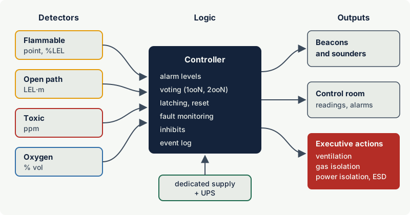
The outputs fall into three groups:
- Indication: the concentration at each detector, shown locally and in the control room.
- Alarms: audible and visual alarms in the area and the control room, distinct from other site alarms.
- Executive actions: automatic or operator-initiated actions such as increasing ventilation, closing gas supply valves, isolating non-Ex electrical equipment, stopping hot work, shutting down process equipment or starting deluge.
When is fixed gas detection required?
There is no single rule that says "install gas detection here". The requirement comes from one of four sources, often several at once.
1. Law and regulation
- In the EU, Annex II of the ATEX workplace directive 1999/92/EC requires that, where necessary, workers be given optical and/or acoustic warnings and be withdrawn before explosion conditions are reached. Where an explosive atmosphere can build up in an occupied area, fixed gas detection is the usual way to meet this. The decision is part of the explosion risk assessment and should be recorded in the Explosion Protection Document.
- Some sector rules prescribe detection directly. For example, US rules for offshore oil and gas operations (30 CFR 250.490) require H2S detection systems in areas where H2S is present or unknown, able to sense at least 10 ppm and alarm at 20 ppm. Coal mining regulations commonly require continuous methane monitoring.
- General health and safety law (exposure control, confined spaces, chemical agents) can require detection where it is the reasonably practicable way to protect people from toxic gas.
2. Codes and standards for specific installations
Installation codes often call for detection in specific rooms: refrigeration machinery rooms (in Europe, EN 378-3 requires refrigerant detection for many systems, as noted in an HSE research review), boiler and gas plant rooms, battery rooms and hydrogen installations, and pressurised rooms and analyser houses, where gas detection at the air inlet and inside the room protects the non-Ex equipment (see pressurised rooms and analyser houses). National fuel gas and building codes add their own requirements.
3. Risk assessment
Most process plant detection exists because a hazard study (HAZOP, layer of protection analysis, fire and explosion risk assessment) found that a release could escalate unless it is detected and acted upon quickly. In this case the study should define what the detection must achieve: which releases, how fast, and what action.
4. Company and insurer standards
Operators and insurers often have their own requirements for detector coverage in process units, compressor houses, loading areas and control building air intakes.
Note: Gas detection is not a substitute for correct area classification and Ex equipment. It reduces the probability that a release goes unnoticed, but detectors can fail, be out of service for maintenance or be in the wrong place. IEC guidance stresses that errors and failures in gas detection may not be self-evident and that detection should be only part of the overall protection strategy.
Design principles step by step
Step 1: define the hazards and the purpose of each detector
List the substances, their hazards and the sources of release (the area classification is a good starting point), and decide the purpose: toxic protection, explosion prevention, oxygen monitoring, or several of these. For a gas that is both toxic and flammable, the toxic hazard usually governs because the exposure limits are far below the LEL. Ammonia, for example, has an EU short-term exposure limit of 50 ppm but an LEL of 15 % vol (150,000 ppm).
Step 2: choose the measuring principle and range
Select sensors that respond to the target gas at the required range in the actual environment: infrared or catalytic for flammable gas in %LEL, electrochemical, semiconductor or other principles for toxic gases in ppm, electrochemical or paramagnetic cells for oxygen. Consider poisons, interfering gases, temperature, humidity, dust and water. See catalytic vs infrared detectors and electrochemical toxic gas sensors. Detectors in hazardous areas need Ex certification for the zone, gas group and temperature class, and performance certification to the relevant gas detection standard where required.
Step 3: decide locations and coverage
Detectors must be where the gas will go: near likely release points, where gas accumulates, at ventilation air intakes, and at the boundary of occupied areas. Gas density, release momentum, ventilation and obstructions decide the details; where to install gas detectors covers this. For large or congested plant, coverage is assessed with geographic or scenario-based mapping (the approach described, for example, in ISA-TR84.00.07). IEC guidance asks for the reasons behind each location to be recorded and for detectors to be accessible for calibration and maintenance.
Step 4: set alarm levels and define actions
For each detector or group, define the alarm levels and what each one does, and write this into a cause and effect matrix. IEC guidance recommends setting the lowest flammable alarm as low as possible without causing false alarms. Typical first alarms for flammable gas lie between 10 and 25 %LEL; toxic alarms start from the exposure limits. See setting gas detector alarm levels.
Then check the timing: the time from release to detection, plus the detector response time, signal processing and any delays, plus the time for the action (valve closure, evacuation) must be shorter than the time to a dangerous condition. IEC guidance lists these delays explicitly and asks that the total stays below what the application allows.
Step 5: design for integrity
IEC guidance asks designers to consider, from the outset, the integrity of the system, redundancy, power supply integrity and fail-safe operation. In practice:
- Fail-safe signals. Faults, loss of power and broken cables must produce a fault indication, not a silent zero. IEC guidance strongly recommends contacts that are closed in the normal (non-alarm) state for power and equipment failure signals.
- Power. A dedicated, clearly marked supply circuit for the gas detection system, with emergency or uninterruptible power where monitoring must continue, and an alarm if the emergency supply fails.
- Redundancy. IEC guidance recommends duplicating or triplicating sensors and control equipment wherever continuous monitoring is essential, so that the failure or removal of one detector does not leave an area unprotected.
- Compensating measures. Plan in advance what happens when detectors are faulty or under calibration: portable detectors, increased ventilation, removal of ignition sources, stopping the gas supply, or shutdown.
- Functional safety. Where gas detection is part of a safety instrumented function with a required safety integrity level (SIL), the whole loop (detector, logic solver, final element) is designed and proof tested to IEC 61511, with IEC 60079-29-3 giving guidance specific to gas detection. See gas detection and functional safety.
Step 6: install, commission and maintain
IEC guidance recommends installing sensors as late as possible in construction, or sealing and marking them as out of service, so that welding and painting do not damage them. Commissioning includes inspection of the installation, a gas test of every detector and sampling point through to the control system, and confirmation that every alarm and action in the cause and effect matrix works. After that, the system needs routine gas testing and calibration (see gas detector calibration and bump testing) and inspection of the Ex equipment to IEC 60079-17.
Voting and alarm logic
A detector can give a false signal (drift, interference, a failed sensor), and an automatic shutdown has its own cost and risk. Voting reduces spurious trips by requiring agreement between detectors:
| Logic | Meaning | Typical use |
|---|---|---|
| 1ooN (one out of N) | Any one detector in alarm | Alarms to warn people; actions with low cost of spurious operation, such as starting ventilation |
| 2ooN (two out of N) | Two detectors in the same group in alarm | Executive actions with a high cost of spurious trip: emergency shutdown, blowdown, deluge |
| Degraded voting | A faulty detector counts as being in alarm, or the vote is reduced (2oo3 becomes 1oo2) | Keeps protection when one detector is out of service |
Voting only works if the geometry supports it. A 2ooN trip assumes that a dangerous gas cloud will reach at least two detectors of the group in time. If the detectors are far apart, a cloud large enough to matter may reach only one, and the voted trip never happens. Mapping studies therefore assess coverage for the voting rule actually used.
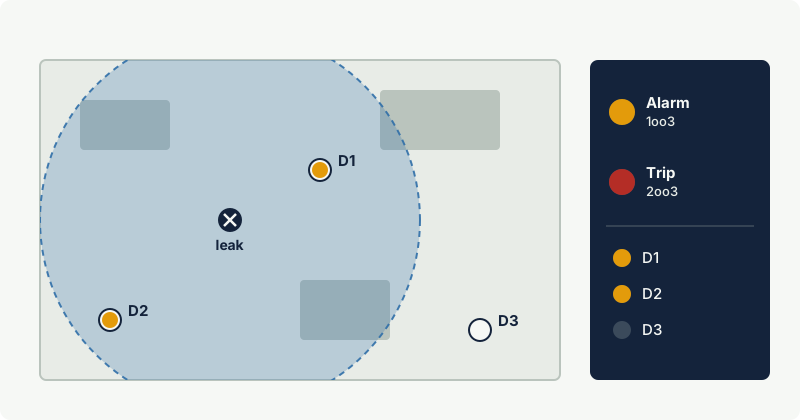
Good alarm logic also includes latching of executive alarms (manual reset after investigation), clear indication of inhibited and faulty detectors, and alarms that are distinct from other site alarms. Inhibits during maintenance must be visible in the control room and controlled by a permit.
Documentation: the system dossier
IEC guidance recommends keeping a dossier for each fixed system: the operating instructions, plans showing all parts of the system with cable and sample tube routes, the manufacturer's manuals, and maintenance and calibration records, updated whenever the installation changes. A practical dossier contains:
- Design basis or detection philosophy: purposes, hazards, standards applied, performance targets.
- Detector schedule: tag, gas, principle, range, location, purpose, alarm levels, voting group.
- Layout drawings and coverage or mapping study, with the reasons for each location.
- Cause and effect matrix for all alarms and actions, with latching and reset rules.
- Safety requirements specification for any safety instrumented functions.
- Certificates: Ex certificates and performance test evidence for detectors and control units.
- Installation, commissioning and loop test records.
- Maintenance and calibration procedures and records, including as-found results.
- Management of change records: any change of process, layout or ventilation should trigger a review of the detection design.
Example: In 2019 two people died from hydrogen sulphide at an oilfield waterflood station in Odessa, Texas. The US Chemical Safety Board found that the fixed H2S detection system was not working: the control panel received no signals from its sensors, so no alarm sounded. The CSB called for documented programmes for installation, calibration, inspection, maintenance and routine operation of detection systems.
Standards and guidance: what covers what
| Document | Scope | Note |
|---|---|---|
| IEC 60079-29-0:2025 | Performance requirements and test methods for flammable, oxygen and toxic gas detectors | Replaced IEC 60079-29-1 and IEC 60079-29-4 in 2025 |
| IEC 60079-29-2:2015 | Selection, installation, use and maintenance of detectors for flammable gases and oxygen | The 2015 edition added open path detection and specific applications, including gas detection as a means of reducing the risk of explosion and monitoring of air inlets |
| IEC 62990-2:2021 (EN IEC 62990-2) | Selection, installation, use and maintenance of detectors for toxic gases and vapours | EN 45544-4:2016, the earlier European guide, was withdrawn in 2023 |
| IEC 60079-29-3:2014 | Guidance on functional safety of fixed gas detection systems | Used with IEC 61508 and IEC 61511 |
| IEC 61511 | Safety instrumented systems for the process industry | Applies where gas detection is part of a SIF |
| IEC 60079-14 and IEC 60079-17 | Installation and inspection of electrical equipment in hazardous areas | Apply to detectors and wiring in classified areas |
| ISA-TR84.00.07 | Evaluation of fire, combustible gas and toxic gas system effectiveness | Performance-based coverage and mapping |
The flammable and toxic guidance documents share the same structure and principles: understand the gas and its behaviour, select equipment that suits the gas and environment, locate detection points with recorded reasons, set alarm levels with a clear purpose, plan for failures and maintenance, test with gas, and keep records. The toxic guidance adds the distinction between exposure measurement (personal monitoring) and safety monitoring (alarms), which matters for alarm settings.
Practical case: an ammonia refrigeration machinery room
A cold store uses an ammonia refrigeration plant in a dedicated machinery room.
- Hazards and purposes. Ammonia is toxic (EU limits 20 ppm over 8 hours and 50 ppm over 15 minutes) and flammable at high concentrations (LEL 15 % vol). It is lighter than air (relative density 0.59), but a cold release with liquid droplets can behave as a heavy cloud at first. Two purposes follow: toxic warning to protect people, and a high-concentration function to protect against ignition.
- Technology. Electrochemical sensors in ppm for the toxic function; a separate high-range sensor for the flammable function, because a ppm sensor cannot measure up to the LEL.
- Locations. Above the compressors and valve stations, at ceiling level where the warm gas collects, near the room exits and in the exhaust duct, with access for testing.
- Actions. A low toxic alarm starts emergency ventilation and warns staff; a higher alarm calls for evacuation and alerts the emergency team. The high-range function isolates electrical equipment that is not suitable for an explosive atmosphere, while the emergency ventilation fans and the detection system itself must stay powered and are selected accordingly.
- Integrity and records. Fault signals, a dedicated power supply, latching high alarms, and a dossier with the cause and effect matrix and test records. National refrigeration safety codes (in Europe, EN 378) set specific requirements for such rooms, which take precedence over this outline.
Common mistakes
- Starting from a detector count instead of the hazards. "One detector every so many metres" without a purpose for each detector leaves gaps at the release points and wastes detectors elsewhere.
- Using gas detection to justify non-Ex equipment without a proper basis. Detection reduces risk but fails silently; it complements, and does not replace, area classification and certified equipment.
- Voting detectors that cannot see the same cloud. A 2ooN trip on widely spaced detectors may never operate for a realistic leak.
- No plan for detectors out of service. Calibration, faults and repairs remove detectors every year. Define compensating measures in advance.
- Undocumented set points and locations. Without recorded reasons, later changes cannot be judged, and the system drifts from its design.
- Forgetting toxic hazards of flammable vapours. All flammable vapours are harmful at small fractions of their LEL, and %LEL detectors do not protect people from toxic exposure.
Frequently asked questions
When is a fixed gas detection system required?
When a law, a sector regulation, an installation code or the site's risk assessment shows that a gas release could harm people or cause an explosion and needs to be detected and acted upon. In the EU, the ATEX workplace directive requires warnings and withdrawal of workers before explosion conditions are reached where necessary, and gas detection is the usual means. Specific rules exist for sectors such as offshore oil and gas, mining and refrigeration.
What standards apply to fixed gas detection systems?
Detector performance is covered by IEC 60079-29-0 (since 2025, replacing IEC 60079-29-1 and IEC 60079-29-4). Selection, installation, use and maintenance are covered by IEC 60079-29-2 for flammable gases and oxygen, and by IEC 62990-2 for toxic gases. Functional safety guidance is in IEC 60079-29-3, used with IEC 61511.
What is 2oo3 voting in gas detection?
It means that two out of a group of three detectors must be in alarm before an automatic action, such as an emergency shutdown, is taken. It reduces trips caused by a single faulty detector. Alarms to warn people are normally given by any single detector, and the voted detectors must be placed so that a dangerous gas cloud reaches at least two of them.
Can gas detection replace Ex equipment in a hazardous area?
Not in general. Gas detection can reduce the risk, for example by isolating non-Ex equipment when gas is detected, but detectors can fail without warning, be out of service or miss a release. Any such arrangement must be justified in the risk assessment and meet the applicable national rules and IEC guidance.
What is EN 45544-4 and is it still valid?
EN 45544-4 was the European guide to the selection, installation, use and maintenance of toxic gas detectors. The 2016 edition was withdrawn in 2023. The current international guidance is IEC 62990-2:2021, published in Europe as EN IEC 62990-2.
Related on excodex
- Where to install gas detectors
- Setting gas detector alarm levels
- Gas detector calibration and bump testing
- Gas detection and functional safety
- Open path gas detectors
- Gas library: /gas; standards spaces IEC 60079-29-2, IEC 60079-29-0, IEC 61511 and ATEX 1999/92/EC; questions in the forum
Standards and further reading
- IEC 60079-29-2:2015, Explosive atmospheres, gas detectors: selection, installation, use and maintenance of detectors for flammable gases and oxygen: https://webstore.iec.ch/en/publication/21961
- IS/IEC 60079-29-2:2007, the first edition of the same guidance as adopted in India, publicly available: https://law.resource.org/pub/in/bis/S05/is.iec.60079.29.2.2007.pdf; IEC webstore (current edition, IEC 60079-29-2:2015): webstore.iec.ch
- IEC 60079-29-0:2025, Explosive atmospheres, gas detection equipment: general requirements and test methods: https://webstore.iec.ch/en/publication/77173
- IEC 60079-29-3:2014, Explosive atmospheres, gas detectors: guidance on functional safety of fixed gas detection systems: https://webstore.iec.ch/publication/645
- IEC 62990-2:2021, Workplace atmospheres, gas detectors: selection, installation, use and maintenance of detectors for toxic gases and vapours (DIN EN IEC 62990-2 catalogue entry): https://www.vde-verlag.de/standards/0400590/din-en-iec-62990-2-vde-0400-990-2-2023-09.html
- EN 45544-4:2016 status (withdrawn): https://www.evs.ee/en/evs-en-45544-4-2016
- Directive 1999/92/EC, Annex II (minimum requirements for workplaces with explosive atmospheres): https://www.legislation.gov.uk/eudr/1999/92/annex/II
- HSE, offshore fire and explosion strategy: fire and gas detection: https://www.hse.gov.uk/offshore/strategy/fgdetect.htm
- ISA-TR84.00.07-2026, Guidance on the evaluation of fire, combustible gas and toxic gas system effectiveness: https://www.isa.org/products/isa-tr84-00-07-2026-guidance-on-the-evaluation-of
- US Chemical Safety Board, executive summary of the investigation into the 2019 hydrogen sulphide release in Odessa, Texas: https://www.csb.gov/assets/1/20/Executive_Summary_from_Final_Report.pdf
This article is general technical information prepared by the excodex editorial team. It does not replace the applicable standards, the equipment certificates and instructions, national regulations or the assessment of a competent person.