How to carry out a gas hazardous area classification step by step (IEC 60079-10-1)
Abstract
A practical ten-step method for gas hazardous area classification under IEC 60079-10-1: data, substances, sources and grades of release, release rate, ventilation, zone type, extent, documentation and review, with a worked example.
A gas hazardous area classification is carried out by identifying every point where a flammable gas, vapour or liquid can escape, deciding how often each release happens (its grade), estimating how much is released and how well the air dilutes it, and from that deriving the zone type and the extent of each zone. IEC 60079-10-1 sets out this "source of release" method, and industry codes can be used alongside it for common equipment. The result is a set of drawings in plan and elevation, supported by data sheets and recorded assumptions, which must be kept up to date when the plant changes.
This article walks through the method in ten steps, shows what each step needs and produces, and finishes with a worked example on an outdoor natural gas skid.
Key points
- IEC 60079-10-1:2020 (edition 3) is the international method for classifying areas with flammable gases, vapours and mists; in the EU the employer's duty to classify comes from Directive 1999/92/EC.
- The core of the method is the list of sources of release: each one gets a grade (continuous, primary or secondary), a release rate and a ventilation assessment.
- The zone type follows from the grade of release combined with the degree of dilution (high, medium, low) and the availability of ventilation (good, fair, poor).
- The extent of a zone depends mainly on the release rate and the dilution; it can be estimated with the standard's charts, with dispersion modelling or from a recognised industry code.
- Catastrophic failures such as vessel rupture are outside the scope of area classification and are handled by other risk assessment.
- The output is not only a drawing: substances, sources, grades, ventilation assumptions and the basis for each extent must be documented so that others can check and update the work.
Before you start: method, scope and team
IEC 60079-10-1 describes several routes to a classification, and most real studies combine them:
| Route | When it fits | Watch out for |
|---|---|---|
| Source of release method | any plant; the reference method of the standard | needs reliable process and ventilation data |
| Industry codes and national standards | equipment covered by a recognised code, for example the Energy Institute's Model Code of Safe Practice Part 15 (EI 15), API RP 505 or codes for natural gas installations | the code's assumptions must match your equipment, pressures and layout |
| Simplified methods | early design or small installations, with conservative assumptions | tends to give larger zones; document why it is conservative |
| Combination | most plants | keep the basis of each zone traceable |
Agree the scope before starting. Area classification addresses releases during normal operation and foreseeable malfunctions. Catastrophic failures, such as the rupture of a vessel or a pipeline, are excluded and belong in the process hazard analysis. Flammable mists are treated in an annex of the standard, combustible dusts in IEC 60079-10-2, and the consequences of ignition are not part of the zoning except through the concept of negligible extent.
The team matters as much as the method. The standard expects competent people who understand the process, the substances, the equipment and the method: typically a process engineer, an operator who knows how the plant is really run (sampling, draining, filter changes) and an explosion protection engineer. One person working from drawings alone usually misses real sources.
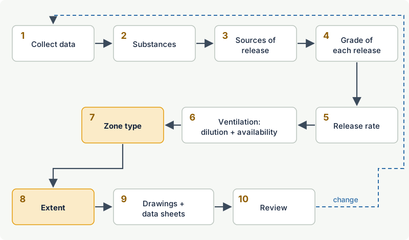
Steps 1 and 2: collect the data and list the substances
Step 1: collect the data
Typical inputs are:
| Input | Used for |
|---|---|
| Process flow diagrams, heat and material balance | substances, temperatures, pressures, phases |
| Piping and instrumentation diagrams | sources of release: flanges, valves, drains, vents, sample points, relief valves |
| Layout drawings, plans and elevations, building drawings | positions, obstructions, openings, pits and trenches |
| Ventilation design, fan data, building openings | degree of dilution and availability |
| Operating and maintenance procedures | which releases happen in normal operation, and how often |
| Leak and maintenance history | realistic grades and hole sizes |
| Site climate data | wind conditions and ambient temperatures |
Step 2: list the flammable substances and their properties
For every substance that can be released, record the properties that drive the classification. IEC 60079-10-1 provides a data sheet format for this in its annex on presentation; the 2020 edition added the upper flammable limit and the source of the data to it.
| Property | Why it matters |
|---|---|
| Lower and upper explosive limits (LEL, UEL) | dilution needed; release characteristic |
| Flash point and boiling point, versus process and ambient temperature | whether a liquid release produces flammable vapour |
| Vapour density relative to air | shape of the zone: rising, neutral or ground-hugging |
| Molar mass, ratio of specific heats | release rate calculation for gases |
| Gas group and temperature class (or autoignition temperature) | not for the zone itself, but for equipment selection |
Use one consistent data source. On excodex, the gas and solvent library gives these values for each substance, for example methane, propane or toluene. For mixtures, use the properties of the actual composition; the most hazardous component does not always govern every property.
Steps 3 and 4: sources of release and their grades
Step 3: identify the sources of release
A source of release is any point from which a flammable substance can escape into the atmosphere in a way that could form an explosive gas atmosphere. Walk the P&IDs line by line and the plant in person, and list every:
- flanged joint, threaded connection and small-bore fitting;
- valve stem packing, pump seal and compressor seal;
- sample point, drain point and vent (including tank vents and breathers);
- relief valve discharge and vent stack outlet;
- loading and unloading connection, filling point, open vessel or open liquid surface;
- opening in equipment that is opened for routine work, such as a filter housing or a pig launcher.
Also consider the inside of equipment where vapour and air coexist, such as the vapour space of a fixed-roof tank. Welded pipework in good condition is not normally treated as a source of release.
Step 4: assign the grade of each release
Each release gets one grade, based on how often and how long it is expected:
- Continuous grade: continuous, or expected frequently or for long periods. Example: the surface of a flammable liquid in a vented fixed-roof tank.
- Primary grade: expected periodically or occasionally during normal operation. Example: a sample point used every shift.
- Secondary grade: not expected in normal operation, and if it happens, only infrequently and for short periods. Example: a flange gasket leak.
One physical source can produce releases of more than one grade, for example a pump seal with a small primary release and a larger secondary release on failure. Each is assessed separately and the resulting zones are combined. The grades are explained in detail in a separate article of this chapter.
Steps 5 and 6: release rate and ventilation
Step 5: estimate the release rate
The release rate drives the extent of the zone. It depends on the form of the release: gas, liquefied gas under pressure, refrigerated liquid, evaporating pool, vapour or mist. IEC 60079-10-1 gives equations for these cases in an annex, with suggested hole cross-sections for secondary releases from typical items such as flanges, valve packings, seals and small-bore connections.
For a gas escaping through a small hole, the flow is choked (sonic) when the absolute pressure upstream exceeds the critical ratio to atmospheric pressure, about 1.8 to 1.9 depending on the gas. The mass release rate is then:
Wg = Cd · S · p · √( γ·M / (Z·R·T) · (2/(γ+1))^((γ+1)/(γ−1)) )
where Cd is the discharge coefficient, S the hole area, p the absolute pressure, γ the ratio of specific heats, M the molar mass, Z the compressibility factor, R the universal gas constant and T the gas temperature. Below the critical pressure ratio a subsonic formula applies.
The release characteristic combines the release rate with the flammability of the gas: Wg / (ρg · LFL), in m³/s, where ρg is the gas density at ambient conditions and LFL is the lower flammable limit as a volume fraction. In the 2020 edition the additional safety factor k that earlier editions applied to the LFL in this expression was removed. The release characteristic is the input for the dilution and extent charts.
Step 6: assess the ventilation
Ventilation is assessed in two independent parts:
- Degree of dilution: high, medium or low. Outdoors it depends on the release characteristic and the wind velocity, read from a chart in the standard; indoors the ventilation flow and the resulting background concentration of gas in the room are also checked. If the background concentration exceeds a critical value chosen for the assessment (a fraction of the LFL, commonly 25 %), dilution is generally treated as low.
- Availability: good (present virtually continuously), fair (expected during normal operation, with infrequent short interruptions) or poor (neither, but no long interruptions expected).
Natural ventilation in open, unobstructed outdoor locations usually gives medium or high dilution with good availability. Pits, trenches, congested modules and buildings need a specific assessment. The details are in the separate article on ventilation.
Step 7: determine the zone type
The grade of release, the degree of dilution and the availability combine into a zone type through a table in IEC 60079-10-1. The pattern is intuitive:
| Grade of release | High dilution, good availability | Medium dilution, good availability | Low dilution |
|---|---|---|---|
| Continuous | non-hazardous (Zone 0 NE) | Zone 0 | Zone 0 |
| Primary | non-hazardous (Zone 1 NE) | Zone 1 | Zone 1 or Zone 0 |
| Secondary | non-hazardous (Zone 2 NE) | Zone 2 | Zone 1 and even Zone 0 |
Fair or poor availability raises the result: a Zone 1 from a primary release with medium dilution becomes "Zone 1 surrounded by Zone 2" when availability is only fair or poor, and high dilution with poor availability no longer reaches non-hazardous. The full matrix, including the fair and poor columns, is given and explained in the ventilation article.
"NE" means negligible extent: in theory a zone exists, but it is so small that an ignition would have negligible consequences, so the place can be treated as non-hazardous. This must be justified, not assumed.
Step 8: determine the extent of each zone
The extent is the distance from the source to the boundary where the concentration has fallen safely below the LFL. Three approaches are common:
- The standard's chart. IEC 60079-10-1 includes a chart that gives a hazardous distance from the release characteristic, with separate curves for jet releases, diffusive releases and heavy gas behaviour. The 2020 edition limited the conditions under which this chart may be used, so read its notes before applying it.
- Dispersion modelling. Integral models or computational fluid dynamics give more realistic shapes, especially for large releases, obstructed areas or buildings. They need validated tools and competent users.
- Industry codes. Codes such as EI 15 give extents for typical equipment based on release rates and conditions. They are efficient, provided the code's assumptions match the plant.
Then turn the distance into a shape. Gases lighter than air such as methane (vapour density 0.554) need the zone extended upwards, with attention to roofs and canopies. Heavier vapours such as propane (1.52) or toluene (3.18) spread at ground level, so include pits, trenches and drains within reach. Round distances up and merge overlapping zones into one envelope.
Steps 9 and 10: document and review
Step 9: document the classification
The documentation must allow someone else to understand, check and update the work. IEC 60079-10-1 asks for drawings, data sheets and tables, and HSE's guidance to the UK regulations sets out the same expectations:
- Drawings in plan and elevation showing every zone and its extent, so that the three-dimensional shape is clear, using consistent symbols (the standard proposes hatching conventions).
- Substance data sheet: each flammable substance with the properties used.
- Source of release schedule: each source with its location, grade, release rate basis, ventilation assessment, zone type and extent basis.
- Assumptions: operating modes considered, ventilation design values, hole sizes, codes used, and any conditions the classification depends on (for example "ventilation fans interlocked with process shutdown").
In the EU, the zone drawings are part of the explosion protection document required by Article 8 of Directive 1999/92/EC, drawn up before work starts and revised after significant changes. They are also the basis for Ex equipment selection and the Ex equipment register.
Step 10: review and keep it current
A classification is valid only while its assumptions hold. Review it through management of change whenever equipment, substances, operating conditions, layout or ventilation change; after any leak that contradicts the assumed grades or extents; and periodically against the plant as it really is, since new walls, buildings and equipment change air movement.
Short-term maintenance does not normally need a new drawing; HSE guidance says the risks of the temporary situation should be controlled through a proportionate risk assessment and the permit-to-work system.
Worked example: outdoor natural gas pressure reduction skid
The example below is simplified to show the logic. The values marked as assumed are illustrative, not design values.
Step 1, data. An outdoor skid on an open concrete pad reduces natural gas from 4 barg to a lower distribution pressure. The skid has inlet and outlet flanges, a filter with a manual vent valve on top, a pressure regulator and a relief valve that discharges to a vent stack at high level. There are no buildings or walls nearby. The filter element is changed every few months; the filter is depressurised and the last gas is released through its vent valve.
Step 2, substances. Natural gas is treated as methane for this example: LEL 4.4 % by volume, vapour density 0.554 (lighter than air), temperature class T1, gas group IIA. For a real installation, check the gas composition; heavier hydrocarbons change the properties.
Steps 3 and 4, sources and grades.
| Source | Grade | Reason |
|---|---|---|
| Flanged joints (three) | secondary | tight in normal operation; leak only after gasket failure |
| Regulator stem seal | secondary | not expected to leak in normal operation |
| Filter vent outlet | primary | gas is released at each filter change, a planned, periodic activity |
| Vent stack outlet | secondary | relief valve lifts only on regulator failure; assessed as a separate source at its outlet |
Step 5, release rate for a flange. Assumed equivalent leak area S = 0.25 mm² (compare with the suggested values in the standard for your gasket type), Cd = 0.75, p = 5.01 bar absolute, T = 288 K, γ = 1.31, M = 16.04 kg/kmol, Z = 1.
Example: The pressure ratio p/pa is about 4.9, above the critical ratio of about 1.84 for γ = 1.31, so the flow is choked. The formula gives Wg ≈ 1.6 × 10⁻⁴ kg/s (about 0.6 kg/h). With ρg = 0.678 kg/m³ for methane at 15 °C and 1.013 bar, and LFL = 0.044, the release characteristic is Wg / (ρg · LFL) ≈ 0.0055 m³/s.
Step 6, ventilation. Open, unobstructed outdoor location with natural ventilation: availability good. The release characteristic is plotted against the wind velocity on the standard's dilution chart, using the indicative outdoor velocity the standard gives for this kind of location. A small secondary leak of this size outdoors falls in the high dilution region, clear of the boundary with medium dilution. The filter vent is different: depressurising the filter housing releases a much larger flow for a short time, and the team assesses it as medium dilution.
Step 7, zone type.
- Flanges and regulator: secondary grade, high dilution, good availability. The standard's table gives non-hazardous (Zone 2 NE), provided the negligible extent is justified and documented. Here the team decides to keep a small Zone 2 around each joint, because the gasket types are mixed and a larger hole size cannot be ruled out; this is a recorded, conservative choice, and with medium dilution the result would be Zone 2 anyway.
- Filter vent: primary grade, medium dilution, good availability: Zone 1 by the table. The team adds a surrounding Zone 2 as a practical margin for larger vent flows and variable wind; this goes beyond the table and is recorded as such.
- Vent stack outlet: assessed separately with the relief valve's discharge rate, which is much larger than a flange leak; it creates its own zone at high level, away from the skid.
Step 8, extent. The hazardous distance r for the flange leak is read from the standard's chart for a jet release (within the chart's stated limits) or calculated with a dispersion model, then rounded up. Because methane is buoyant, the Zone 2 spheres around flanges are drawn with at least the same extent upwards.
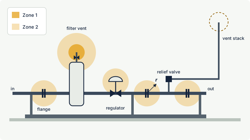
Design improvement. The only Zone 1 on the skid comes from venting the filter locally. If the filter depressurisation is piped to the vent stack, the release at working level disappears, the closed filter vent valve becomes a secondary source at most, and the Zone 1 on the skid is removed. The vent stack outlet then becomes a primary source as well and its zone must be reassessed, but it sits at high level, in free air and away from people and equipment. This is the typical pattern of a good classification study: it shows where a small design change avoids a demanding zone.
Step 9, documentation. The drawing shows the skid in plan and elevation with all zones; the source schedule records the four sources, the assumed hole size, the ventilation basis, the zone type and the basis of each extent; the assumptions list "gas composition as per supplier specification" and "no enclosure to be added around the skid without review".
Common mistakes
- Starting from the drawing instead of the plant. Sources that exist only in practice, such as a drain hose or a filter vented locally, never appear on a P&ID. Walk the plant with operators.
- Using an industry code outside its assumptions. Code distances assume certain pressures, release sizes and ventilation. Applying them to a congested module or a building without checking is a common source of under-classification.
- Ignoring the shape of the zone. A circle in plan for a heavy vapour misses the pit next to it; a sphere for hydrogen under a roof misses accumulation at the ceiling.
- Writing "good ventilation" without evidence. Availability and dilution must be justified: fan redundancy, interlocks, measured flows, or the open layout of an outdoor site.
- Treating the classification as finished. New walls, enclosures, acoustic hoods and extra equipment change the air movement. Without management of change the drawings become wrong silently.
- Classifying for consequences. Upgrading a zone because an explosion would be severe confuses zone type with risk. Address severe consequences with a higher EPL, layout or other measures, and keep the zone honest.
Frequently asked questions
Who is allowed to carry out a hazardous area classification?
There is no single licence, but the work must be done by competent people who know the process, the substances, the equipment and the method. In the EU the employer remains responsible under Directive 1999/92/EC. Personnel competence schemes for explosive atmospheres include units on area classification.
Can an industry code be used instead of calculations?
Yes, where the code covers your equipment and its assumptions match your conditions. IEC 60079-10-1 explicitly allows industry codes and national standards, and most studies combine them with calculations for items the code does not cover. Record which code, which edition and which figure or table was used for each zone.
What documents does a hazardous area classification produce?
The minimum is a set of zone drawings in plan and elevation, a list of flammable substances with their properties, and a schedule of sources of release with grade, ventilation, zone type and extent basis. The assumptions behind the study should be written down. In the EU these documents form part of the explosion protection document.
When must a hazardous area classification be reviewed?
Whenever something that it depends on changes: the substances, operating conditions, equipment, layout, buildings or ventilation. It should also be reviewed after leaks or incidents and periodically as part of normal management. Short-term maintenance is normally handled by the permit system rather than by redrawing the zones.
Does the 2020 edition of IEC 60079-10-1 cover fuel gas installations?
Yes. The 2020 edition removed an earlier scope exemption for commercial and industrial applications using only low-pressure fuel gas for appliances, and added guidance on fuel gas installations, so boiler houses and gas-fired equipment can be classified with the same method. Specific national or industry codes for gas installations can still be used where they apply.
Related on excodex
- Hazardous area zones explained: Zone 0, Zone 1 and Zone 2
- Grades of release: continuous, primary and secondary
- Ventilation in area classification: degree of dilution and availability
- Estimating the extent of a hazardous zone: release rates and dilution
- The Explosion Protection Document (EPD) and area classification drawings under ATEX 1999/92/EC
- Typical hazardous area examples: tank vents, pumps, compressors and loading points
- Tools: gas and solvent library, standards spaces IEC 60079-10-1, EI 15, API RP 505, forum
Standards and further reading
- IEC 60079-10-1:2020 (edition 3.0), Explosive atmospheres, Part 10-1: Classification of areas, explosive gas atmospheres. A fourth edition was circulated as a committee draft for vote in 2025; check the current edition before use. IEC webstore page
- IEC 60079-10-2, Classification of areas for combustible dust atmospheres.
- IEC 60079-14, Electrical installations design, selection and erection.
- Energy Institute, Model Code of Safe Practice Part 15, area classification code for installations handling flammable fluids (EI 15).
- API RP 505, recommended practice for classification of locations for electrical installations at petroleum facilities using the zone system.
- Directive 1999/92/EC, Article 8 on the explosion protection document: legislation.gov.uk copy of Article 8
- HSE, Hazardous area classification and control of ignition sources: hse.gov.uk
- HSE, L138 Dangerous substances and explosive atmospheres, Approved Code of Practice and guidance (free PDF): hse.gov.uk
- Santon, Ivings, Webber, Kelsey (Health and Safety Laboratory), New methods for hazardous area classification for explosive gas atmospheres, IChemE Hazards XXIII, 2012, background to the ventilation method of the earlier editions: icheme.org
- Ineris, Principes de ventilation en zone ATEX (in French), 2022: ineris.fr
This article is general technical information prepared by the excodex editorial team. It does not replace the applicable standards, the equipment certificates and instructions, national regulations or the assessment of a competent person.