Estimating the extent of a hazardous zone: release rates and dilution
Abstract
How far does a hazardous zone reach? Hole sizes, release rate equations for gas, liquid and two-phase leaks, the release characteristic, the IEC 60079-10-1 charts, EI 15 and API RP 505, with a worked natural gas example.
The extent of a hazardous zone is the distance from a source of release to the point where the flammable gas or vapour has been diluted safely below its lower flammable limit (LFL). It is estimated in four steps: choose a credible hole size, calculate the release rate from the pressure, temperature and phase of the fluid, convert it into a release characteristic (the air flow needed to dilute the release to the LFL), and turn that into a distance with the charts of IEC 60079-10-1, a dispersion model or an industry code such as EI 15 or API RP 505. The hole size assumption usually has more influence on the answer than any other input.
This article explains each step for gas, liquid and two-phase releases, shows how the standard's charts are used without reproducing them, compares the alternative industry codes, and works through a natural gas example with every assumption stated.
Key points
- The extent of a zone is driven mainly by the release rate and the degree of dilution; gas density, obstacles and the direction of the release then shape it.
- For secondary releases, IEC 60079-10-1 suggests hole cross-sections by type of item, for example from about 0.025 mm² up to 2.5 mm² for flanges with compressed fibre gaskets depending on whether the opening can grow; catastrophic failures are excluded.
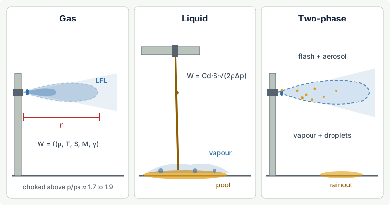
- A gas leak is choked (sonic) when the absolute pressure upstream exceeds about 1.7 to 1.9 times atmospheric pressure, depending on the gas; above that, the mass release rate rises in proportion to the absolute pressure and the hole area.
- A liquid below its boiling point produces flammable vapour only by evaporation from a pool or from a mist; a liquefied gas under pressure flashes partly to vapour at once and forms fine droplets, so it behaves as a much larger gas release.
- The release characteristic, release rate divided by gas density and LFL, in m³/s, is the common input to the dilution chart and the hazardous distance chart of IEC 60079-10-1:2020.
- For a momentum jet, the distance to a given concentration grows roughly with the square root of the release rate: ten times the hole area gives about three times the distance.
- EI 15 (5th edition, 2024) and API RP 505 offer tabulated or typical extents for common equipment; they are valid only where their assumptions match the plant.
What "extent" means
A release creates a cloud in which the concentration falls from 100 % at the hole to zero far away. The hazardous distance is where it has dropped below the LFL with a margin; the 2020 edition of IEC 60079-10-1 added a figure illustrating this dilution volume. The extent is therefore a judged envelope around a hypothetical leak, not a measurement. It is also a separate answer from the zone type, which comes from the grade of release and the ventilation (see the ventilation article).
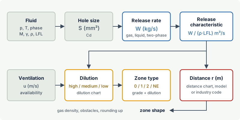
Step 1: choose a credible hole size
For a continuous or primary release the size of the opening is usually known: a vent, a sample point, a drain valve. For a secondary release, a leak that should not happen at all, the size has to be assumed. This is the most judgement-heavy part of the whole study.
IEC 60079-10-1 gives a table of suggested hole cross-sections for secondary releases in its annex on sources of release. It distinguishes three situations for each type of item: openings that are not expected to grow, openings that may grow (for example by erosion), and openings that may grow up to a severe failure such as a gasket blow-out. The values below are from Table B.1 of the 2015 edition, as reproduced in public worked examples. The 2020 edition keeps a Table B.1 with the same title and its published list of changes does not mention it, but confirm the values against the edition you work to:
| Item | Opening not expected to grow | Opening may grow | Severe failure |
|---|---|---|---|
| Flange, compressed fibre gasket | 0.025 to 0.25 mm² | 0.25 to 2.5 mm² | gasket segment between two bolts × gasket thickness |
| Flange, spiral wound gasket | 0.025 mm² | 0.25 mm² | segment between two bolts × gasket thickness |
| Valve stem packing | 0.25 mm² | 2.5 mm² | manufacturer data, not less than 2.5 mm² |
| Pump and compressor seals | not applicable | 1 to 5 mm² | manufacturer data, not less than 5 mm² |
The standard advises taking the lower values only where conditions are good and failure is unlikely, and the higher values where equipment runs close to its design limits or in adverse conditions such as vibration, temperature cycling or corrosion.
Write the hole size and the reason down for every source, so that a reviewer can challenge one number instead of the whole drawing. Research by the UK Health and Safety Laboratory stressed that the expected hole size must not be underestimated, because it dominates the result. Catastrophic failures, such as a full-bore rupture, are out of scope: they belong to the process hazard analysis, not to zoning.
Industry codes take a different route. The Energy Institute's risk-based approach, used in EI 15, links hole sizes to release frequency levels derived from leak statistics, including the UK HSE Hydrocarbon Release Database.
Step 2: calculate the release rate
The release rate W is the mass of flammable material escaping per second. How it is calculated depends on the form of the release: gas, liquid, liquefied gas under pressure, refrigerated liquid, vapour or mist. IEC 60079-10-1:2020 describes these forms and gives the equations in its annex on sources of release.
Gas and vapour releases
For a gas escaping through a small hole, the decisive question is whether the flow is choked. When the absolute pressure upstream exceeds the critical pressure, about 1.84 times atmospheric for methane, about 1.9 for hydrogen and about 1.7 for propane and heavier hydrocarbons, the velocity in the hole reaches the speed of sound and the mass flow becomes:
Wg = Cd · S · p · √( γ·M / (Z·R·T) · (2/(γ+1))^((γ+1)/(γ−1)) )
with Cd the discharge coefficient, S the hole area, p the absolute upstream pressure, γ the ratio of specific heats, M the molar mass, Z the compressibility factor, R the gas constant and T the gas temperature in kelvin. Below the critical pressure a subsonic equation applies, which gives smaller flows.
The discharge coefficient depends on the shape of the opening: close to 1 for smooth, rounded openings and clearly lower for sharp-edged orifices. For irregular leak paths such as gasket leaks, a value of 0.75 is common in published worked examples; a value close to 1 is the conservative choice when the shape is unknown. In the choked regime the release rate is directly proportional to S and to the absolute pressure: doubling either doubles W.
Liquid releases
A liquid escaping through a hole follows Bernoulli's equation:
W = Cd · S · √( 2 · ρ · Δp )
with ρ the liquid density and Δp the pressure difference across the hole. The liquid mass rate is often large, but it is not what creates the zone. What matters is the rate at which flammable vapour forms:
- A liquid below its flash point at the handling temperature forms little or no flammable vapour, unless it is sprayed as a mist; mists need their own assessment, treated in an annex of the standard.
- A liquid above its flash point but below its boiling point, such as toluene (flash point 4 °C) at ambient temperature, spreads into a pool. The vapour release is the evaporation rate from the pool surface, which depends on pool area, vapour pressure, molar mass, temperature and air velocity over the pool. The 2020 edition updated the evaporation equations and the chart of specific evaporation rate that goes with them.
- Kerbs, drains and sloped floors limit the pool size, and with it the extent.
Liquefied gases and two-phase releases
A liquefied gas held under pressure above its normal boiling point, such as propane or butane, behaves very differently. On release, part of the liquid flashes to vapour immediately; the energy for this comes from cooling the rest of the liquid to its boiling point. The remaining liquid is shattered into fine droplets that partly evaporate in the jet as it entrains warm air, and partly rain out to form a cold pool.
The flash fraction can be estimated from an energy balance:
flash fraction ≈ cp · (T − Tb) / hv
with cp the liquid heat capacity, T the liquid temperature, Tb the normal boiling point and hv the heat of vaporisation. For propane at 15 °C (Tb about −42 °C) this gives roughly 30 % flashing immediately.
Three simplifications are common, from least to most conservative:
- Take the flashed vapour only, and treat the rest as a pool.
- Take the flashed vapour plus an entrained fraction of fine droplets.
- Treat the whole release as vapour.
Unless rainout can be justified, the third option is the safe default for area classification. The release rate itself is often estimated with the liquid equation above, using the pressure difference between the line and the atmosphere: for a flashing flow this tends to overestimate the mass rate, which errs on the safe side.
Refrigerated liquids such as liquefied natural gas form a boiling pool whose cold vapour is initially heavier than air.
Step 3: from release rate to release characteristic
IEC 60079-10-1:2020 normalises every release into a release characteristic:
release characteristic = W / (ρg · LFL) in m³/s
where ρg is the density of the gas or vapour at ambient conditions and LFL is the lower flammable limit as a volume fraction. Physically, it is the volume flow of air needed to dilute the release exactly to its LFL. The 2020 edition removed the safety factor k that the 2015 edition applied to the LFL in this expression.
The release characteristic is used twice:
- Dilution. Plotted against the ventilation velocity on the standard's dilution chart, it gives high, medium or low dilution.
- Distance. Plotted on the hazardous distance chart, it gives an estimate of the extent.
Indoors, the background concentration is also checked: approximately Xb = f · Qg / Qa, with Qg the volume flow of gas (summed over releases that can occur together), Qa the ventilation air flow and f a mixing factor (1 for ideal mixing, higher for poor mixing). It is compared with a critical value chosen by the assessor, most often 25 % of the LFL.
Step 4: from release characteristic to hazardous distance
The chart in IEC 60079-10-1
The standard's annex on estimating hazardous areas contains a log-log chart with the release characteristic on the horizontal axis and the hazardous distance on the vertical axis. It has three curves:
| Curve | Applies to | Typical example |
|---|---|---|
| Jet release | unimpeded, high-velocity releases where the jet momentum does the mixing | a pressurised gas leak from a flange, a vent at high velocity |
| Diffusive release | low-velocity releases, or jets that hit an obstacle and lose their momentum | an impinged jet, a low-pressure vent, evaporation from a surface |
| Heavy gas | releases that spread along the ground because the gas is denser than air | heavy vapours from pools, cold vapour from liquefied gases |
Using the chart is straightforward: calculate the release characteristic, choose the curve that matches the behaviour of the release, read the distance and round up. The 2020 edition restricted the conditions under which the chart may be used, so read its notes before relying on it; for large releases, complex geometry, enclosed spaces or unusual substances, a dispersion model is more appropriate.
Choosing the curve matters more than reading it precisely. A jet that hits a nearby wall, pipe rack or the ground loses its momentum and should be treated as diffusive, which gives a larger distance.
How the distance scales
Free-jet theory explains why hole size is so important. In a momentum jet, the concentration on the axis falls in inverse proportion to the distance from the hole, scaled by the effective diameter of the source. For a choked release, the effective diameter grows with the hole diameter and with the square root of the pressure, so the distance to a fixed concentration grows roughly with the square root of the mass release rate.
In practice: ten times the hole area, or ten times the absolute pressure, gives about three times the hazardous distance for a jet.
Turning a distance into a shape
The distance is only a radius. Lighter-than-air gases such as methane (vapour density 0.554) or hydrogen (0.0696) need the envelope extended upwards, especially under roofs; heavier vapours such as propane (1.52) or toluene (3.18) need a wider envelope near the ground, including pits and drains. A jet of unpredictable direction is drawn in all directions. The standard's annex on presentation suggests typical shapes for low-pressure gas, high-pressure gas, liquefied gas and evaporating liquids.
Alternative routes: EI 15 and API RP 505
IEC 60079-10-1 allows recognised industry codes and national standards to be used instead of, or alongside, its own calculation. Two dominate in the oil and gas industries.
| IEC 60079-10-1 | EI 15 (Energy Institute) | API RP 505 | |
|---|---|---|---|
| Scope | any flammable gas, vapour or mist | installations handling flammable fluids, mainly petroleum, now including hydrogen | petroleum facilities, zone system for electrical installations |
| Method | source of release: hole size, release rate, ventilation, charts | point source approach with hazard radii by fluid category, pressure and release frequency level; direct examples for common facilities | mainly typical figures for common equipment and facility types; an informative alternate, source-based method |
| Hole sizes | suggested values per type of item | linked to release frequency levels from leak data | built into the typical figures |
| Strength | traceable for any substance | consistent, quick for common fluids and equipment | quick, widely used in North America |
| Watch out for | the chart's limits of use | fluid category and conditions must match | figures assume particular ventilation and arrangements |
EI 15, the Energy Institute's Model Code of Safe Practice Part 15, is in its 5th edition (October 2024). It groups fluids into categories, broadly: A for liquefied gases such as LPG, B for liquids released above their boiling point such as hot process streams, C for liquids above their flash point but below their boiling point, and for mists, G(i) for typical natural gas and G(ii) for refinery hydrogen streams. Hazard radii are tabulated by category, pressure and hole size, supported by dispersion modelling; the 5th edition added pure hydrogen and higher-pressure releases.
API RP 505, the American Petroleum Institute's recommended practice for Class I, Zone 0, 1 and 2 locations at petroleum facilities, is in its 2nd edition (2018). Most users apply its typical figures, which give extents for common equipment; an informative annex also describes an alternate method that classifies by individual sources of release.
Whichever code is used, record the edition, the table or figure, and why the plant matches the code's assumptions.
Worked example: natural gas leak at a metering skid
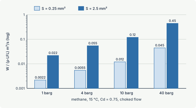
Situation. The values are illustrative, not design values. An outdoor metering skid handles natural gas at 10 barg (11.0 bar absolute) and 15 °C. The gas is treated as methane: LFL 4.4 % by volume, molar mass 16.04 kg/kmol, γ = 1.31, density at ambient conditions 0.678 kg/m³. Source: a flange with a spiral wound gasket, secondary grade of release.
Hole size. Two assumptions are compared: S = 0.25 mm² (an opening that may grow for this gasket type) and S = 2.5 mm² (a larger leak, as the team might assume if vibration and thermal cycling are present). Cd = 0.75, Z = 1.
Example: The pressure ratio is 11.0 / 1.013 ≈ 10.9, well above the critical ratio of about 1.84, so the flow is choked. For S = 0.25 mm² the equation gives Wg ≈ 3.6 × 10⁻⁴ kg/s (about 1.3 kg/h). The release characteristic is 3.6 × 10⁻⁴ / (0.678 × 0.044) ≈ 0.012 m³/s. For S = 2.5 mm², everything scales by ten: Wg ≈ 3.6 × 10⁻³ kg/s (about 13 kg/h) and a release characteristic of about 0.12 m³/s.
Dilution. Outdoors in an open location, availability is good. Each release characteristic is plotted against the standard's indicative wind velocity for the location; the result, high or medium dilution, decides between negligible extent (Zone 2 NE) and Zone 2.
Distance. With nothing close to the flange, both leaks are unimpeded jets and the jet curve applies; whatever value the chart gives, the larger hole gives about √10 ≈ 3.2 times the distance. If a cable tray runs 0.5 m from the flange, the jet may impinge and the diffusive curve becomes the honest choice.
The same leak indoors. Suppose the skid were inside a 320 m³ room ventilated at 0.53 m³/s, with moderately poor mixing (f = 2):
| Hole area | Gas volume flow | Background concentration | Fraction of LFL |
|---|---|---|---|
| 0.25 mm² | 5.3 × 10⁻⁴ m³/s | 2 × 5.3 × 10⁻⁴ / 0.53 ≈ 0.20 % vol | about 5 % |
| 2.5 mm² | 5.3 × 10⁻³ m³/s | 2 × 5.3 × 10⁻³ / 0.53 ≈ 2.0 % vol | about 45 % |
With the larger hole the background concentration exceeds the commonly used critical value of 25 % of the LFL, so dilution is low and the secondary release gives Zone 1 or worse instead of Zone 2. One assumption about a gasket changes the classification of the whole room.
A liquid and a liquefied gas for comparison. Through the same 2.5 mm² hole (Cd 0.75):
- Toluene at 5 bar pressure difference (liquid density about 870 kg/m³) leaks at about 0.055 kg/s, roughly 3.8 litres per minute. It does not flash: the zone depends on the pool and its evaporation, so containing and draining the pool matters more than refining the calculation.
- Liquid propane at 15 bar pressure difference (liquid density about 500 kg/m³) leaks at about 0.073 kg/s. About 30 % flashes at once. If all of it is treated as vapour (gas density about 1.87 kg/m³, LFL 1.7 %), the release characteristic is about 0.073 / (1.87 × 0.017) ≈ 2.3 m³/s: some twenty times the methane leak at 10 barg through the same hole, and with a heavy, ground-hugging cloud.
Common mistakes
- Choosing the smallest hole size in the table by default. The suggested ranges are for different conditions. Justify the value for each source and do not underestimate it.
- Using the liquid mass rate as the vapour release rate for a non-boiling liquid. For liquids below their boiling point the vapour comes from the pool; for liquefied gases, by contrast, ignoring the droplets underestimates the release.
- Applying the jet curve to an impinged release. A jet that hits a nearby obstacle behaves as a diffusive release and travels further at low velocity.
- Taking a code distance outside its assumptions. EI 15 and API RP 505 distances assume particular fluids, pressures, ventilation and arrangements. Check each one before copying it.
- Drawing a circle and stopping. The radius must become a three-dimensional shape that reflects gas density, release direction, pits, drains and roofs.
Frequently asked questions
How do you calculate the extent of a hazardous area?
Estimate the release rate from a credible hole size and the process conditions, divide it by the gas density and the LFL to get the release characteristic, and read the hazardous distance from the chart in IEC 60079-10-1, a dispersion model or an industry code. Then shape the zone according to gas density, release direction and obstacles, round up, and document every assumption.
What hole size should be used for a flange leak?
IEC 60079-10-1 suggests ranges by gasket type and condition, for example from 0.025 mm² up to 2.5 mm² for compressed fibre gaskets, and a gasket segment between two bolts for a severe failure. Choose within the range according to operating conditions, maintenance and leak history, and record the reason. Industry codes such as EI 15 link hole sizes to release frequency levels instead.
Why do LPG releases give much larger zones than natural gas?
Liquefied gases escape as liquid, which carries far more mass through a given hole than gas, and part of it flashes to vapour at once while the rest forms droplets that evaporate in the jet. The vapour is also heavier than air and spreads along the ground. Together these effects give release characteristics many times larger than for a gas leak through the same hole.
Can I use EI 15 or API RP 505 instead of IEC 60079-10-1?
IEC 60079-10-1 allows recognised industry codes and national standards where they apply. Many studies combine them: code distances for standard equipment, calculation for items the code does not cover. National regulations or client specifications may require a particular method, so check them first, and record the code edition and table used.
Related on excodex
- How to carry out a gas hazardous area classification step by step
- Grades of release: continuous, primary and secondary
- Ventilation in area classification: degree of dilution and availability
- Typical hazardous area examples: tank vents, pumps, compressors and loading points
- Vapour density: which gases rise, which sink, and why it matters
- Flammable mists and sprays: the overlooked explosion hazard
- Tools: gas and solvent library, standards spaces IEC 60079-10-1, EI 15, API RP 505, forum
Standards and further reading
- IEC 60079-10-1:2020 (edition 3.0), Explosive atmospheres, Part 10-1: Classification of areas, explosive gas atmospheres. Annexes cover sources of release and release rates, ventilation and dilution, and estimation of hazardous areas. A fourth edition was circulated as a committee draft in 2025. Preview with contents and list of changes
- Energy Institute, Model Code of Safe Practice Part 15: Area classification for installations handling flammable fluids (EI 15), 5th edition, 2024: energyinst.org
- Energy Institute, A risk-based approach to hazardous area classification, 2nd edition, 2016: energyinst.org
- API RP 505, recommended practice for classification of locations for electrical installations at petroleum facilities classified as Class I, Zone 0, Zone 1 and Zone 2, 2nd edition, 2018.
- Santon, Ivings, Webber, Kelsey (Health and Safety Laboratory), New methods for hazardous area classification for explosive gas atmospheres, IChemE Hazards XXIII, 2012: icheme.org
- Nalpanis and others, Independent review of some aspects of IP15 area classification, IChemE Symposium Series 154, 2008, dispersion modelling behind the code's fluid categories: icheme.org
- NIST Chemistry WebBook, propane phase change and heat capacity data used in the flash fraction estimate: webbook.nist.gov
This article is general technical information prepared by the excodex editorial team. It does not replace the applicable standards, the equipment certificates and instructions, national regulations or the assessment of a competent person.