Typical hazardous area examples: tank vents, pumps, compressors and loading points
Abstract
Typical zones around fixed-roof tanks and vents, pumps, compressors and road tanker loading, how EI 15, API RP 505 and prescriptive tables describe them, a worked US example with distances, and why every case still needs a site-specific check.
Around common equipment, hazardous areas follow recognisable patterns. The vapour space of a vented fixed-roof tank holding a liquid above its flash point is Zone 0, its vent is surrounded by Zone 1 and then Zone 2, and the bund is often Zone 2 up to the top of its wall. Pump and compressor seals usually create Zone 2, with Zone 1 close to seals that release in normal operation, and loading points give Zone 1 at open hatches and Zone 2 around closed couplings. Industry codes such as EI 15 and API RP 505 put distances on these patterns, but the real extent depends on the fluid, pressure, ventilation and layout, so every typical example must be checked against the actual installation.
This article walks through tanks, pumps, compressors and loading points, explains how the main codes present typical areas, shows a published set of distances with its limits, and lists what to check before copying a typical figure.
Key points
- Typical examples and code figures are shortcuts for standard equipment under standard conditions; IEC 60079-10-1 accepts them only where the code's assumptions match the plant.
- Inside a vented fixed-roof tank with a volatile liquid the vapour space is normally Zone 0; the vent is a primary source during filling and breathing, giving Zone 1 near the outlet and Zone 2 beyond.
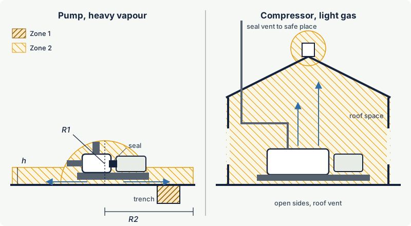
- Pump and compressor seals are usually secondary sources giving Zone 2; seals expected to release in normal operation are primary and add a Zone 1 close to the seal.
- Heavier-than-air vapours need a low-level extension of the zone at grade, and pits, trenches and drains within a zone are normally classified more onerously because vapour collects in them.
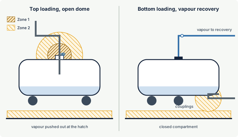
- Top loading through an open hatch creates Zone 1 at the hatch; bottom loading with vapour recovery reduces the sources to the couplings and leaves mostly Zone 2.
- Prescriptive tables give a sense of scale but use their own system: the US OSHA bulk plant table (29 CFR 1910.106, Table H-18) puts a tank vent in Division 1 within 5 ft (1.5 m) of the open end and Division 2 from 5 to 10 ft (3 m). These are Division boundaries for flammable liquids at bulk plants, not zone extents.
- Enclosing equipment changes everything: a compressor house or acoustic hood is a building that needs its own ventilation assessment, often under IEC 60079-13.
How industry codes describe typical areas
IEC 60079-10-1 is a method, not a catalogue: it explains how to derive zones from sources of release, ventilation and release rates. Industry codes add catalogues of typical cases, and the standard allows them to be used where they apply. They work in three ways:
| Approach | How it works | Examples |
|---|---|---|
| Direct examples or typical figures | drawings of standard installations with zone types and distances | EI 15 direct examples for common facilities such as storage tanks and road tanker loading; API RP 505 typical figures for pumps, compressors, vents and loading |
| Point source | a hazard radius per source from tables by fluid category, pressure and hole size | EI 15 point source approach |
| Prescriptive tables in regulations or fire codes | fixed distances per type of location | US OSHA tables for flammable liquid bulk plants and service stations |
EI 15, the Energy Institute's Model Code of Safe Practice Part 15 (5th edition, 2024), combines direct examples for common facilities with a point source approach and a risk-based approach that links hole sizes to release frequency. Its fluid categories (A for liquefied gases such as LPG, B for liquids released above their boiling point, C for liquids above their flash point and for mists, G(i) for natural gas, G(ii) for refinery hydrogen) are a convenient way to describe what a source handles.
API RP 505 (2nd edition, 2018) is the American Petroleum Institute's recommended practice for classifying petroleum facility locations into Class I, Zone 0, 1 and 2. Its figures show typical extents for equipment in open, adequately ventilated and enclosed locations, with separate sections for different facility types, and an informative alternate method based on individual sources.
The two codes do not give identical answers for the same equipment, because they use different assumptions about release sizes, ventilation and margins. Pick one basis per study and say which.
Storage tanks and tank vents
Fixed-roof tanks
A fixed-roof atmospheric tank with a free vent breathes: vapour leaves through the vent when the tank is filled or warmed by the sun, and air enters when it is emptied or cools. If the stored liquid is above its flash point, or close to it, the vapour space contains a flammable mixture much of the time.
The European Commission's guide to Directive 1999/92/EC uses exactly this case as its gas example: an outdoor tank, filled and emptied regularly, holding a liquid whose flash point is close to the average annual temperature, with vapours heavier than air. The inside of the tank is Zone 0, the area around the pressure equalising opening is Zone 1, and an area around the tank is Zone 2 because, in rare adverse weather, vapour can run down the shell. The guide stresses that the size of the outside zones depends on the liquid, the opening, the filling frequency and level change, and the natural ventilation.
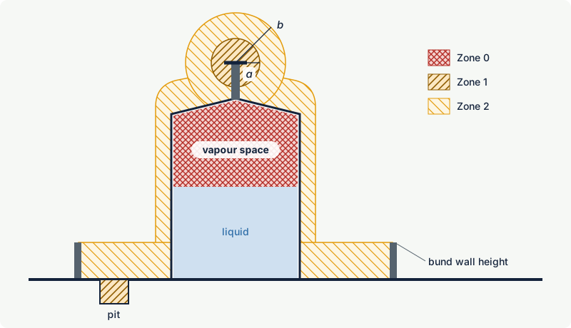
Points to check for tanks:
- The liquid. A liquid stored well below its flash point, such as most diesel and kerosene grades in temperate climates, may not create a Zone 0 inside at all; heated storage or hot product changes that. Kerosene, for example, has a flash point of 38 °C in the excodex library, so tank heating or a hot climate matters.
- The vent. A pressure and vacuum valve releases less often than a free vent, a flame arrester does not change the zone, and a vent routed to vapour recovery or treatment removes the vent as a primary source.
- The bund. Heavy vapours collect in the bund. Codes commonly classify the bunded area up to the top of the bund wall; sumps and drain pits within it are often classified more onerously.
- Inerting. A nitrogen-blanketed vapour space is not Zone 0 while the blanket works, but the classification must cover blanket failure and the vent.
Floating-roof tanks
A floating roof sits on the liquid and removes most of the vapour space. The space above the roof and inside the shell still receives vapour from the rim seal, especially when the roof is low, so codes classify it: the OSHA bulk plant table, for example, makes the area above the roof and within the shell Division 1. Workers on a floating roof are in that area.
Pumps
A pump handling a flammable liquid has one main source of release: the shaft seal. Its grade depends on the seal design and condition. IEC 60079-10-1 lists seals of pumps, compressors and valves among the secondary sources when they are not expected to release in normal operation, and among the primary sources when they are. Other sources are the casing flanges, drain and vent valves used for maintenance, and small-bore connections.
The typical result is:
- Zone 2 around the pump for a secondary seal release, with a radius that depends on the fluid category, pressure and hole size.
- A low-level extension for liquids whose vapours are heavier than air, such as n-hexane (vapour density 2.98) or benzene (2.7): a flat layer of Zone 2 at grade that reaches further than the zone around the seal.
- Zone 1 close to the seal where the seal is expected to weep in normal operation, or where drains are opened routinely.
- Pits, trenches and sumps inside the zone classified more onerously, often Zone 1, because heavy vapour flows into them and stays there.
Indoors, the extent and the zone type depend on the room ventilation. Typical code figures for enclosed pump rooms are larger than for open-air pumps, and inadequately ventilated rooms can become Zone 1 throughout. Seal-less designs (canned motor or magnetic drive pumps) and double seals with a barrier fluid can reduce the grade of release, which is a design lever worth using.
Compressors
Gas compressors have more sources than pumps and handle gas at higher pressure:
- Shaft seals of centrifugal compressors and rod packings of reciprocating compressors, with their vents and drains;
- distance pieces of reciprocating machines, which can collect leaked gas;
- lube oil and seal oil systems, where dissolved gas comes out of solution in tanks and reservoirs;
- many flanges, valves, small-bore connections and instrument tubing.
Seal and packing vents should be piped to a safe location; if they discharge locally, they become primary sources. Outdoors, a compressor in open air is typically surrounded by Zone 2. The difficulty starts when the compressor is housed.
Shelters and compressor houses. A roof traps lighter-than-air gases such as methane (vapour density 0.554) or hydrogen (0.0696). A shelter with open sides and good roof ventilation may be close to open-air conditions; a closed compressor house is a room whose classification depends on its ventilation rate, the availability of the fans, and the release rate of the largest credible leak. IEC 60079-10-1 includes in its examples annex a compressor facility handling natural gas, classified in plan and elevation, which is a good reference for the method.
Acoustic hoods and enclosures. Hoods around compressors, turbines and engines create small, poorly ventilated volumes. They are normally ventilated mechanically and treated as artificially ventilated rooms; IEC 60079-13 covers such rooms and gives guidance for gas turbine enclosures in particular. See pressurised rooms and analyser houses.
Loading and unloading points
Road tankers, rail tank cars and drum filling stations are classic Zone 1 locations because they combine routine connections, open hatches and vapour displacement.
Top loading through an open dome. The incoming liquid pushes vapour out of the hatch at every loading, a primary release in normal operation. The result is Zone 1 close to the hatch and Zone 2 around it; splash loading increases vapour generation and static charging. The extent must cover all positions where vehicles may stand, not just the marked bay.
Bottom loading with vapour recovery. The compartment stays closed and the displaced vapour returns to the plant through a vapour hose. The remaining sources are the couplings, released when hoses are disconnected, which typically gives a small Zone 2 around the couplings and a low Zone 2 at grade. This is one of the clearest cases where a process design choice reduces the classification.
Drums and containers. Filling openings and vents give Zone 1 close to the opening and Zone 2 around it, with a low-level extension indoors for heavy vapours.
Static electricity is as important as the zones at loading points. Bonding of the vehicle, restricted initial filling velocities and avoiding splash filling are part of the same assessment; see static electricity as an ignition source.
A published example with distances: the US Division table
The US Occupational Safety and Health Administration publishes, in 29 CFR 1910.106, tables of electrical hazardous areas for flammable liquid bulk plants and service stations. They use the Division system (Class I, Group D), where Division 1 roughly covers Zone 0 plus Zone 1 and Division 2 roughly corresponds to Zone 2. Selected rows of the bulk plant table (Table H-18), converted to metres:
Warning: The distances below are Division boundaries from a US prescriptive table. They are not Zone 0, 1 or 2 extents and must not be copied onto an IEC or ATEX zone drawing. A zone drawing needs its own basis: a calculation to IEC 60079-10-1 or a recognised zone-based code such as EI 15 or API RP 505.
| Location | Division | Extent of classified area |
|---|---|---|
| Tank vent | 1 | within 5 ft (1.5 m) of the open end, in all directions |
| Tank vent | 2 | between 5 and 10 ft (1.5 to 3 m) of the open end |
| Aboveground tank shell, ends, roof and dike area | 2 | within 10 ft (3 m) of the shell, ends or roof; inside dikes up to the top of the dike |
| Floating roof tank | 1 | area above the roof and within the shell |
| Pumps, meters and similar devices, outdoors | 2 | within 3 ft (0.9 m) in all directions, plus up to 18 in (0.46 m) above grade within 10 ft (3 m) horizontally |
| Pumps, meters and similar devices, indoors | 2 | within 5 ft (1.5 m) in all directions, plus up to 3 ft (0.9 m) above floor within 25 ft (7.6 m) horizontally |
| Tank vehicle loading through open dome | 1 | within 3 ft (0.9 m) of the edge of the dome |
| Tank vehicle loading through open dome | 2 | between 3 and 5 ft (0.9 to 1.5 m) of the edge of the dome |
| Bottom loading with vapour recovery | 2 | within 3 ft (0.9 m) of the connections, plus up to 18 in (0.46 m) above grade within 10 ft (3 m) |
| Pits without mechanical ventilation | 1 | entire pit if any part lies within a Division 1 or 2 area |
Read these figures with their context: they apply to flammable liquids handled at or near atmospheric pressure at bulk plants, with open-air or adequately ventilated conditions, in the Division system. They say nothing about high-pressure gas, liquefied gases, hot process streams or congested process units, and they cannot simply be relabelled as zones. They are useful as a sense of scale and as an illustration of how prescriptive codes work.
Why typical examples are only a starting point
A typical figure carries hidden assumptions. Before using one, check:
| Question | Why it matters |
|---|---|
| Is the fluid the same category? | LPG, hot hydrocarbons and hydrogen give much larger or differently shaped zones than a stable liquid |
| Are pressure and temperature within the code's range? | release rate rises with pressure; liquids above their boiling point flash |
| Is the location as open as the code assumes? | walls, roofs, congestion and pits reduce dilution and change zone type and extent |
| Are there more sources nearby? | overlapping zones merge; several releases indoors add up |
| Do operations match normal practice? | routine draining, sampling or hose disconnection can make a secondary source primary |
| Where does vapour go? | drains, cable trenches and openings in buildings can carry it beyond the drawn zone |
When the answer to any of these is "no" or "not sure", calculate the source with the method in estimating the extent of a hazardous zone, or use dispersion modelling, and document why the typical figure was not used.
Common mistakes
- Copying a figure from another site or another code. Distances depend on fluid, pressure, ventilation and the code's margins. A drawing from a similar plant is a reference, not a basis.
- Treating Division distances as zone distances. A Division 1 area contains both what would be Zone 0 and Zone 1; the boundaries and the equipment rules differ.
- Forgetting the low-level extension. Heavy vapours spread at grade far beyond the zone around the source and into pits and cable trenches.
- Ignoring the vehicle positions. Loading zones must cover every position a tanker may occupy, not just the ideal one.
- Housing equipment without reclassifying. Adding a roof, walls or an acoustic hood to a pump or compressor turns an open-air classification into an indoor one.
- Using typical figures for unusual fluids. Hydrogen, LPG, hot oils above their flash point and mists need specific assessment.
Frequently asked questions
What zone is around a tank vent?
For a free vent on a fixed-roof tank holding a liquid above its flash point, typical practice is Zone 1 close to the vent outlet, surrounded by Zone 2, with the vapour space inside the tank as Zone 0. The distances depend on the liquid, filling rate and vent size; for comparison, the US OSHA bulk plant table uses Division 1 within 1.5 m and Division 2 to 3 m from the open end, but these are Division boundaries, not zone extents.
Is the area around a pump Zone 1 or Zone 2?
Usually Zone 2, because a mechanical seal is not expected to leak in normal operation. Where the seal type releases in normal operation, or drains are opened routinely, a Zone 1 is added close to the source. Heavy vapours need a low-level Zone 2 extension at grade, and pits within the zone are classified more onerously.
Can I use API RP 505 or EI 15 figures in Europe?
IEC 60079-10-1, used for ATEX classification, allows recognised industry codes where they apply, and EI 15 is widely used in Europe for petroleum installations. The code's assumptions must match the plant, the edition and figure used must be recorded, and the result must still meet the national rules that transpose Directive 1999/92/EC.
Does vapour recovery change the hazardous area at a loading point?
Yes. With bottom loading and vapour recovery the compartment stays closed, so the open hatch, the largest primary source in top loading, disappears. Typically only a small Zone 2 around the couplings and a low-level Zone 2 remain, provided the vapour system is maintained and its own vents are classified.
How is a compressor house classified?
As an enclosed space whose classification depends on the release rates of the compressor seals and other sources, the ventilation rate and the reliability of the fans. With adequate, reliable ventilation it is often Zone 2; with poor ventilation it can be Zone 1. Seal vents should be piped outside, and gas detection with automatic actions is common.
Related on excodex
- Grades of release: continuous, primary and secondary
- Estimating the extent of a hazardous zone: release rates and dilution
- Zones vs Divisions: IEC and ATEX zones compared with NEC Class I Division 1 and 2
- Fuel stations and LPG autogas: hazardous areas around dispensers, tanks and vents
- Vapour density: which gases rise, which sink, and why it matters
- Pressurised rooms and analyser houses: making an area non-hazardous by ventilation
- Tools: gas and solvent library, standards spaces EI 15, API RP 505, IEC 60079-10-1, NEC 500 to 506, forum
Standards and further reading
- IEC 60079-10-1:2020, Classification of areas, explosive gas atmospheres, including an examples annex with a natural gas compressor facility and a table of industry codes: preview with contents
- Energy Institute, Model Code of Safe Practice Part 15: Area classification for installations handling flammable fluids (EI 15), 5th edition, 2024: energyinst.org
- API RP 505, classification of locations for electrical installations at petroleum facilities classified as Class I, Zone 0, Zone 1 and Zone 2, 2nd edition, 2018.
- IEC 60079-13:2017, equipment protection by pressurized room "p" and artificially ventilated room "v", including guidance for gas turbine enclosures.
- US OSHA, 29 CFR 1910.106, flammable liquids, tables of electrical equipment hazardous areas for bulk plants and service stations: osha.gov
- European Commission, Non-binding guide to good practice for implementing Directive 1999/92/EC, with the tank zoning example: EU Publications Office
- Nalpanis and others, Independent review of some aspects of IP15 area classification, IChemE Symposium Series 154, 2008: icheme.org
This article is general technical information prepared by the excodex editorial team. It does not replace the applicable standards, the equipment certificates and instructions, national regulations or the assessment of a competent person.