Fuel stations and LPG autogas: hazardous areas around dispensers, tanks and vents
Abstract
How hazardous areas are classified at petrol stations and LPG autogas sites: typical Zone 0, 1 and 2 extents around dispensers, tank fill points, vents and tanker connections, why LPG behaves differently, and which Ex equipment is used.
At a fuel station the hazardous areas are small but always present: Zone 0 inside storage tanks, tank chambers and interceptors; Zone 1 close to tank vents, fill connections, tanker delivery points and around the dispenser up to about 1.2 m above ground within hose reach; and Zone 2 in a wider band around these sources. Their extents come from industry codes rather than from a calculation at every site, for example the EI/APEA "Blue Book" in the UK and Ireland, NFPA 30A and OSHA rules in the US, and national regulations elsewhere. LPG autogas is different because it is stored as a pressurised liquid and its vapour is heavier than air, so zones reach down to ground level and drains, pits and basements nearby need particular attention.
This article explains the classification practice, typical zones for petrol, diesel and LPG, the equipment used in them, and the mistakes that most often turn up on forecourts.
Key points
- Petrol gives off flammable vapour at any normal ambient temperature (its flash point is around -40 °C) and the vapour is heavier than air, so zones are biased towards the ground and into pits and chambers.
- Diesel has a flash point above 55 °C under the European specification, so on its own it normally creates no hazardous area at ambient temperature; mixed petrol and diesel sites are classified for petrol.
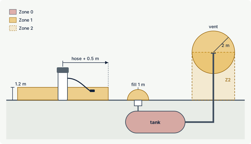
- Irish guidance based on the Blue Book gives nominal zones such as: Zone 1 within 1 m of tanker delivery connections and Zone 2 within 4 m; Zone 1 within 2 m of a tank vent without vapour recovery; and, around a dispenser, a zone of hose length plus 0.5 m radius up to 1.2 m above ground (Zone 1 without Stage II vapour recovery, Zone 2 with it).
- US rules classify the dispenser enclosure as Division 1 up to 1.2 m (4 ft) and a band up to 0.45 m (18 in) above grade within 6 m (20 ft) of the dispenser as Division 2.
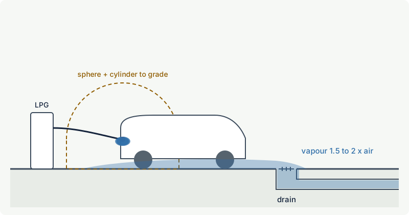
- LPG vapour (propane and butane) is 1.5 to 2 times as dense as air. Codes classify around tank connections, tanker transfer points, relief valve outlets and dispensers, and they require drains and pits near LPG equipment to be avoided, sealed or monitored.
- Equipment inside the zones must be certified for them: the dispenser as a whole (to EN 13617-1 for liquid fuels, which is limited to group IIA fuels), submersible pumps, tank gauging probes (usually intrinsically safe, for Zone 0) and anything electrical in chambers and sumps.
- In a US industry compilation of 176 refuelling fires that appeared to be static related, 87 occurred after the person refuelling had got back into the vehicle and then touched the nozzle; the compiler could not document any fire started by a mobile phone.
The fuels and why they create zones
| Fuel | Flash point | Vapour relative to air | Gas group, T-class | Zone driver |
|---|---|---|---|---|
| Petrol (gasoline) | about -40 °C | heavier | IIA, T3 | vapour at any ambient temperature, displaced from tanks during filling |
| Diesel | above 55 °C (EU spec.) | heavier | IIA, T3 | normally none at ambient temperature |
| LPG autogas (propane, butane) | gas at ambient | 1.52 (propane), 2.01 (butane) | IIA, T2 | pressurised liquid; releases flash to a large vapour volume |
Petrol is always above its flash point at ambient temperature, so every tank, chamber and vent that holds or breathes petrol vapour is a source. Diesel's flash point is above any normal ambient temperature, so diesel-only facilities are usually not zoned unless the fuel is heated or sprayed as a mist; fuel oil no. 2 in the gas library has a flash point of 52 °C, the minimum of the US specification. LPG is stored as a liquid under its own vapour pressure; any liquid release vaporises and expands by roughly 250 times, cools the surroundings, and forms a dense cloud that hugs the ground.
All three are gas group IIA. EN 13617-1, the European safety standard for fuel dispensers, explicitly covers only fuels of group IIA, which is a reminder that fuels outside that group (hydrogen, and potentially some special blends) need separately designed equipment. Hydrogen refuelling is covered in hydrogen production and refuelling stations.
How classification is done at filling stations
Fuel stations are one of the few places where area classification is mostly done from nominal (typical) zone dimensions in an industry code rather than from a release calculation for each source. The codes condense long experience with standard equipment, open-air forecourts and good maintenance:
- UK and Ireland: Design, construction, modification, maintenance and decommissioning of filling stations, the "Blue Book", published by the Energy Institute and APEA (4th edition, April 2018). It covers hazardous area recommendations including longer hoses, LPG sections aligned with industry LPG codes, and guidance on EV charging points. Ireland's Health and Safety Authority publishes a summary of nominal zones based on it.
- United States: NFPA 30A (motor fuel dispensing facilities), and the federal OSHA tables in 29 CFR 1910.106 for service stations and 1910.110 for LPG, written in the Class I Division system.
- Elsewhere: national fuel station regulations and codes, many of them derived from the same sources. For larger petroleum installations, the Energy Institute's area classification code (EI 15) is widely used, and LPG codes often reference it.
The nominal zones are a starting point, not a substitute for judgement. A competent person must check that the site matches the assumptions of the code (open forecourt, standard equipment, normal canopy height) and extend the zones where it does not: forecourts partly enclosed by buildings, below-grade areas, unusual vent positions, very high throughput or non-standard equipment. The result is recorded on plan and elevation drawings in the explosion protection document. Where a code and a site-specific assessment give different extents, the larger one may be applied.
Petrol forecourts: typical zones
The table summarises the nominal zones in the Irish guidance based on the Blue Book. Bracketed values are those set in Irish legislation where they differ. They are typical values for the situation described; site conditions can change them. The Irish summary refers to the 3rd edition of the Blue Book, and the 4th edition (2018) revised the hazardous area recommendations, for example for longer hoses, so use the current edition for design.
| Source | Zone 0 | Zone 1 | Zone 2 |
|---|---|---|---|
| Storage tank interior (vapour space) | inside the tank | ||
| Access chamber or pit with tanker delivery connections | inside the chamber | ||
| Tanker delivery and vapour return connections | 1 m radius, down to ground | 4 m radius | |
| Delivery hose route (tanker to tank) | 1 m radius along the hose | ||
| Below-ground fill point | 1 m from the chamber edge | 4.25 m from a direct fill manhole centre | |
| Tank vent without Stage Ib vapour recovery | 2 m (1.5 m) radius | radial zone extending to ground | |
| Tank vent with Stage Ib vapour recovery | 2 m radius, extending to ground | ||
| Oil separator (interceptor) | inside the separator | inside its access chamber; 1 m around its vent | 2 m from the chamber edge; below the vent down to ground |
| Dispenser, without Stage II vapour recovery | hose length + 0.5 m (4.25 m) radius, up to 1.2 m above ground | ||
| Dispenser, with Stage II vapour recovery | hose length + 0.5 m (4.25 m) radius, up to 1.2 m above ground |
Some features worth understanding:
- The dispenser zone is low and wide. Petrol vapour from a nozzle and a vehicle filler neck is heavy, so the zone extends to the full reach of the hose but only to 1.2 m above ground. Longer hoses mean larger zones.
- Inside the dispenser the hydraulic section (meters, valves, pipework) is a hazardous zone defined by the dispenser manufacturer under its certification, while the electronics head is normally separated from it. Changing or adding components inside a dispenser therefore affects its Ex certification.
- Vapour recovery changes the zones. Stage I (Stage Ib in the Irish summary) returns vapour displaced from the tank to the road tanker during deliveries, so the vent no longer breathes out large volumes. Stage II returns vapour displaced from vehicle tanks back to the storage tank. In the EU, Directive 2009/126/EC requires Stage II systems capturing at least 85 % of the vapour at new or substantially refurbished stations above 500 m³ a year (100 m³ under living accommodation) and at existing stations above 3000 m³ a year from 2018.
- Tanker deliveries create temporary zones around the tanker's couplings and the fill points. They exist only during the delivery but must be respected: no other vehicles, no hot work, no non-Ex equipment in that area while the tanker is connected.
- Chambers and pits that are within or below a zone take the most severe classification of their surroundings, because heavy vapour flows into them and stays there.
The US approach
The OSHA table for service stations (29 CFR 1910.106) uses Divisions. In summary:
| Source | Division 1 | Division 2 |
|---|---|---|
| Dispenser | inside the enclosure up to 1.2 m (4 ft) above its base, and 0.45 m (18 in) horizontally around it; any pit below grade | up to 0.45 m (18 in) above grade within 6 m (20 ft) of the enclosure outdoors (7.5 m, 25 ft, indoors with gravity ventilation) |
| Tank vent discharging upward | within 0.9 m (3 ft) of the open end | 0.9 to 1.5 m (3 to 5 ft) from the open end |
| Tank fill opening | pits and spaces below grade | up to 0.45 m above grade within 3 m (10 ft) of a loose fill connection, 1.5 m (5 ft) of a tight fill connection |
| Lubrication or service room | any pit | up to 0.45 m above the floor throughout the room |
NFPA 30A, the current model code, is written in the same terms and is widely adopted by US jurisdictions. The comparison of Divisions with Zones is explained in zones vs divisions.
LPG autogas: heavier than air and under pressure
An LPG autogas installation has a pressurised storage vessel (above or below ground), a pump, a dispenser with a breakaway coupling and a filling nozzle, a road tanker connection, and pressure relief valves. Every connection that is made and broken in normal operation releases a small amount of LPG, and every relief valve is a potential large release.
What this means for classification:
- Zones reach the ground. The US LPG table classifies, for example, the area within 4.5 m (15 ft) of tanker transfer connections and outdoor pumps, plus the cylindrical volume between the horizontal equator of that sphere and the ground, as Division 2, with Division 1 within 1.5 m (5 ft) of the transfer connections. The same logic appears in Zone-based codes.
- Drains, pits and basements are the danger points. The Hong Kong code of practice for LPG filling stations, for example, asks that drains and pits within 3 m of the tank manhole, dispenser or fill connection be avoided, or else securely covered or sealed, and that pits housing tank fittings or dispensing manifolds have a means to detect and disperse LPG vapour.
- Relief valves discharge upward. Relief valve outlets are piped vertically so that the jet entrains air and disperses before the gas can sink. The Hong Kong code, for example, asks for vent pipes at least 3 m above ground, allows no fixed electrical equipment in the direct path of discharge, and classifies 0.5 m in other directions around the outlet as Zone 2.
Typical zone extents for LPG in the Hong Kong code of practice illustrate the scale:
| Source | Zone 1 | Zone 2 |
|---|---|---|
| LPG storage vessel | within 1.5 m of the vessel connections and shell | up to 1.5 m above ground within 3 m of the manhole assembly |
| Road tanker unloading | within 1.5 m of the fill connection | 1.5 m to 4.5 m from the fill connection |
| Relief valve discharge | no fixed electrical equipment in the direct discharge path | within 0.5 m in other directions |
| Dispenser | interior as defined by the manufacturer; surrounding area Zone 1 to a specified extent |
The US table classifies the LPG dispenser enclosure, 0.45 m around it up to 1.2 m above its base and any pit beneath as Division 1, and a band up to 0.45 m above grade within 6 m of the enclosure as Division 2, the same pattern as for petrol.
LPG sites usually also have emergency shutdown valves on the vessel outlets, fill line and at the dispenser, closed by emergency stop buttons, and often fixed gas detection near the dispenser, pump and pits. The Hong Kong code, for instance, requires an audible alarm at 20 % of the LFL. Installation guidance often quotes positions around 0.3 m from the floor for gases heavier than air such as LPG, and pits are obvious candidates, but the right position follows the likely release, the gas behaviour and the airflow (IEC 60079-29-2); see where to install gas detectors and vapour density.
Equipment in the zones
| Item | Typical location | Typical requirement |
|---|---|---|
| Dispenser hydraulics (pulsers, solenoid valves, meters) | Zone 1 inside the housing | certified as part of the dispenser, for example flameproof, encapsulated or intrinsically safe components |
| Submersible pump in the tank | Zone 0 / Zone 1 | motor and junction box certified for the location, usually flameproof |
| Tank gauging probes, leak sensors in interstitial spaces and sumps | Zone 0 / Zone 1 | intrinsically safe, category 1G (EPL Ga) for Zone 0 |
| Electrical items in tank chambers, sumps, dispenser pits | Zone 0 or Zone 1 | avoid where possible; otherwise certified for the zone |
| Forecourt and canopy lighting | normally above or outside the zones | check the height against the zone extents; Ex luminaires if inside |
| Payment terminals, displays, EV chargers, vending machines | outside the zones | position outside the nominal zones with margin |
| Emergency stop buttons | often near dispensers | certified for the zone if located within it |
For petrol, equipment must be suitable for at least gas group IIA and temperature class T3, the usual classification for petrol. LPG alone would need T2, but mixed sites use IIA T3 throughout. Zone 0 needs category 1G (EPL Ga), Zone 1 category 2G (Gb) and Zone 2 category 3G (Gc), as explained in Equipment Protection Levels.
Customers' vehicles are not Ex equipment. The zones and the operating rules (engine off, no smoking, dispensing only with the nozzle attended or with automatic shut-off) are designed so that normal vehicle presence is acceptable. This is a deliberate risk-based decision built into the codes; it does not mean that other non-Ex equipment can be placed in the zones.
Electrical installations on forecourts also need periodic inspection. The Irish guidance, for example, asks for testing of the electrical installation at least every three years by a competent electrician familiar with explosive atmospheres; the general method is in inspection of Ex installations.
Worked example: placing an EV charger on a forecourt
A station owner wants to add an EV charging point 3.5 m from a petrol dispenser. The dispenser has 3.75 m hoses and no Stage II vapour recovery. The charger's socket and electronics are between 0.8 and 1.6 m above ground.
- Dispenser zone: hose length + 0.5 m = 4.25 m radius, Zone 1 up to 1.2 m above ground.
- Check the charger: at 3.5 m it is inside the 4.25 m radius, and its lower part (0.8 to 1.2 m) is inside the Zone 1 band. A charger is a source of sparks and heat and is not certified for Zone 1.
- Other zones: the tanker delivery stand and fill points are 9 m away; the Zone 2 around the tanker connections (4 m) does not reach the proposed position, but the tanker's route across the forecourt must also stay clear of vehicles that are charging.
- Decision: move the charger to at least 4.25 m from the dispenser, plus a practical margin for hose movement and parked vehicles, outside any tanker delivery zone and away from drains from the forecourt. Record the new layout on the zone drawing.
The Blue Book contains specific guidance on EV charging at filling stations, which should be followed in the UK and Ireland. The same method applies to payment kiosks, air and water machines and any other new equipment on a forecourt.
Static electricity and mobile phones
Static electricity is a real ignition source at the pump. A US industry compilation published in 2010 collected 176 reports of refuelling fires from 1992 onwards that appeared to be static related. In 87 of them the person refuelling had got back into the vehicle and then touched the nozzle, after charging their body by sliding across the seat. The compiler could not document any fire that was started by a mobile phone. The practical rules: stay outside the vehicle while refuelling, touch the metal of the car away from the filler before handling the nozzle, and place portable containers on the ground when filling them, never in a vehicle or on a plastic bed liner. The physics is explained in static electricity as an ignition source.
Mobile phones are still not certified equipment, and many operators prohibit their use at the dispenser as a matter of site policy. Staff using phones, tablets or handheld terminals inside the zones need equipment suitable for the zone, see portable electronics in hazardous areas.
Common mistakes
- Forgetting below-ground spaces. Drains, cable pits and inspection chambers near dispensers or LPG equipment collect heavy vapour. Seal them, move them, or classify and monitor them.
- Placing new equipment from a plan without the zone drawing. EV chargers, kiosks, vending machines and lighting columns are regularly installed inside dispenser or vent zones. Check every addition against the drawing.
- Assuming vapour recovery makes zones disappear. Stage I and II reduce the zone grade (from Zone 1 to Zone 2) but do not remove the hazardous area; failed vapour recovery reverts it.
- Vent pipes next to openings. Vent outlets near windows, air intakes or roof edges of buildings carry vapour into places that are not classified. Keep vents clear of openings and check the zone around them.
- Treating LPG like petrol. LPG is a pressurised liquid with larger potential releases, relief valves, emergency shutdown requirements and a stronger tendency to collect in low points. It needs its own code and assessment.
- Using IIA dispensers for non-IIA fuels. Liquid fuel dispensers are designed for group IIA fuels. Different fuels need a separate review of gas group and temperature class.
Frequently asked questions
What zone is a petrol pump?
The inside of the dispenser's hydraulic section is a hazardous zone defined by the manufacturer's certification. Around the dispenser, codes such as the Blue Book give a zone of hose length plus 0.5 m radius up to 1.2 m above ground: Zone 1 without Stage II vapour recovery and Zone 2 with it. In the US the equivalent is Division 1 inside the enclosure and Division 2 up to 0.45 m above grade within 6 m.
How far does the hazardous area extend around a fuel tank vent?
In the Irish summary of the Blue Book, Zone 1 extends 2 m around a vent without Stage I vapour recovery, with a Zone 2 extending down to the ground; with vapour recovery the 2 m zone becomes Zone 2. US rules classify 0.9 m (3 ft) around an upward vent as Division 1 and 0.9 to 1.5 m as Division 2. Site conditions can require larger zones.
Is a diesel-only fuel station a hazardous area?
Usually not at ambient temperature, because diesel's flash point (above 55 °C in the European specification) is well above normal ambient temperatures. Exceptions are heated diesel, spray or mist releases, and tanks or vents shared with petrol or contaminated with lighter fuels. The assessment must confirm this for the site.
Why is LPG more dangerous than petrol at filling stations?
LPG is stored under pressure as a liquid, so a leak releases a large volume of gas very quickly, and the vapour is 1.5 to 2 times as dense as air, so it flows into drains, pits and basements. That is why LPG sites have emergency shutdown valves, often gas detection at low level, and rules for drains and pits near LPG equipment.
Can you use a mobile phone at a petrol station?
Mobile phones are not certified for hazardous areas, and many stations prohibit their use at the pump. However, an industry compilation of static-related refuelling fires found that about half followed the person getting back into the vehicle during refuelling, and could not document any fire started by a phone. Staying outside the vehicle while refuelling is the most effective personal precaution.
Which standard applies to fuel dispensers?
In Europe, EN 13617-1 sets the safety requirements for the construction and performance of metering pumps, dispensers and remote pumping units for liquid fuels of group IIA, and dispensers are placed on the market as ATEX equipment. LPG dispensers have their own standard, EN 14678-1. In the US, dispensers are listed to standards referenced by NFPA 30A.
Related on excodex
- Typical hazardous area examples: tank vents, pumps, compressors and loading points
- Methane, propane and LPG: properties every safety engineer should know
- Vapour density: which gases rise, which sink, and why it matters
- Zones vs Divisions: IEC and ATEX zones compared with NEC
- Hydrogen production and refuelling stations
- Tools: propane, butane and LPG in the gas library, standards spaces EI 15, IEC 60079-10-1 and ATEX 1999/92/EC, forum
Standards and further reading
- Energy Institute and APEA, Design, construction, modification, maintenance and decommissioning of filling stations (the Blue Book), 4th edition, 2018: publishing.energyinst.org
- Health and Safety Authority (Ireland), Fire and explosion risks in service stations, including nominal zone distances: hsa.ie
- EN 13617-1:2021, Petrol filling stations, safety requirements for construction and performance of metering pumps, dispensers and remote pumping units: evs.ee
- EN 14678-1, LPG equipment and accessories for automotive filling stations, Part 1: Dispensers.
- Energy Institute, Model code of safe practice Part 15 (EI 15), area classification for installations handling flammable fluids.
- NFPA 30A, Code for Motor Fuel Dispensing Facilities and Repair Garages; NFPA 58, Liquefied Petroleum Gas Code.
- OSHA 29 CFR 1910.106 (flammable liquids, service stations table): osha.gov and 1910.110 (LP-gas, electrical area classification table): osha.gov
- Electrical and Mechanical Services Department, Hong Kong, Code of practice for LPG filling stations (2020): emsd.gov.hk
- EU summary of Directive 2009/126/EC on Stage II petrol vapour recovery: eur-lex.europa.eu
- Fires at refuelling sites that appear to be static related (US industry compilation, 2010): pei.org
This article is general technical information prepared by the excodex editorial team. It does not replace the applicable standards, the equipment certificates and instructions, national regulations or the assessment of a competent person.