Hydrogen production and refuelling stations: hazardous areas, detection and equipment
Abstract
Electrolysers, compressors, high-pressure storage and dispensers create hydrogen release sources at pressures of 70 MPa and more. How to classify the hazardous areas, select IIC or IIB+H2 equipment, and design gas and flame detection for hydrogen production and refuelling sites.
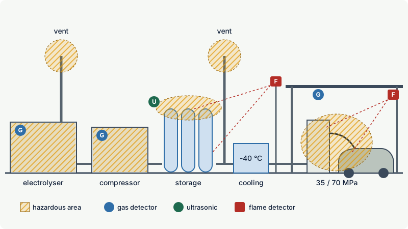
Hydrogen production and refuelling stations combine several hydrogen release sources: the electrolyser and its gas separators, compressors, high-pressure buffer storage, pre-cooling and the dispenser, which fills vehicles at 35 or 70 MPa nominal pressure. Each source is classified with IEC 60079-10-1 like any other gas installation, but the results differ from a hydrocarbon plant: releases are high-pressure jets, enclosures must be ventilated at the top, and the equipment must be gas group IIC (or IIB+H2) with temperature class T1 for hydrogen alone. Because hydrogen is invisible to infrared gas detectors and burns with an almost invisible flame, detection relies on hydrogen-capable point sensors, often ultrasonic leak detectors outdoors, and UV, UV/IR or hydrogen-capable multi-spectrum IR flame detectors.
This article goes through the main units of a station, the typical release sources and how they are classified, the selection of Ex equipment, and a detection concept for leaks and fires.
Key points
- The station-level standard for gaseous hydrogen fuelling stations is ISO 19880-1 (2020). It covers production, compression, storage, pre-cooling and dispensing, and contains sections on hazardous areas, hydrogen detection systems and safety distances for vent stacks.
- Electrolysers are covered by ISO 22734-1 (2025), which replaced ISO 22734:2019. They produce hydrogen and oxygen; both outlets need safe venting, and the oxygen side brings an oxygen-enrichment hazard that Ex certification does not cover.
- Vehicle fuelling pressures are 35 MPa and 70 MPa nominal, with maximum vehicle tank pressures of 43.8 and 87.5 MPa. Fast fills at 70 MPa use hydrogen pre-cooled to about -40 °C.
- Hazardous areas around hydrogen equipment are classified with IEC 60079-10-1. Typical release sources are compressor seals and packings, valve stems, fittings, vent stack outlets and the dispenser nozzle and hose.
- Ex equipment must be IIC or IIB+H2. Temperature class T1 is enough for hydrogen alone; a multi-fuel forecourt with petrol needs at least T3.
- Infrared gas detectors cannot detect hydrogen. Use catalytic, thermal conductivity, electrochemical or semiconductor sensors, at high points of enclosures, and add ultrasonic leak detection for high-pressure outdoor plant.
- Hydrogen fires are almost invisible in daylight. Flame detectors must be proven for hydrogen fires; UV, UV/IR and suitable multi-spectrum IR detectors and thermal imaging are used.
The parts of a hydrogen station
A station that produces hydrogen on site typically contains the units below. Stations supplied by road with compressed or liquid hydrogen replace the electrolyser with a delivery and storage area, but the rest is similar.
| Unit | What it does | Main hazards |
|---|---|---|
| Electrolyser | splits water into hydrogen and oxygen in a stack, separates gas from electrolyte | hydrogen at the stack and separators, hydrogen in oxygen (crossover), oxygen enrichment, caustic electrolyte in alkaline types |
| Purification and drying | removes oxygen traces and water | hydrogen leaks, hot catalytic de-oxidiser |
| Compressor | raises pressure in one or more stages | seal and packing leaks, vibration and fatigue of small-bore tubing, hot discharge gas |
| Buffer storage | stores gas at high pressure in cylinders, often in pressure banks | valve and fitting leaks, pressure relief discharge via vent stack |
| Pre-cooling | cools gas to about -40 °C before dispensing | low temperatures on materials, refrigerant hazards |
| Dispenser | controls the fill to the vehicle via hose, breakaway coupling and nozzle | leaks at the nozzle, hose and breakaway; small releases at connection and disconnection |
| Vent stacks | discharge hydrogen from relief valves, purges and depressurisation | flammable atmosphere and possible fire at the outlet |
Pressures and temperatures
Fuelling protocols for light-duty vehicles define two nominal working pressures: 35 MPa (maximum vehicle tank pressure 43.8 MPa) and 70 MPa (maximum 87.5 MPa), each 125 % of the nominal value. The gas heats up when it is compressed into the vehicle tank, and the tanks are rated to 85 °C, so fast fills at 70 MPa use gas pre-cooled to about -40 °C. Station storage must be at a higher pressure than the vehicle tank at the end of the fill, so the high-pressure storage of a 70 MPa station operates well above 70 MPa.
At these pressures hydrogen is dense: about 24 g per litre at 35 MPa and about 40 g per litre at 70 MPa. A small hole releases a choked jet at high velocity, which dominates the extent of the hazardous area.
Hazardous area classification
Method
ISO 19880-1 has sections on hazardous areas, including the area around the dispenser, and refers normatively to the IEC 60079 series. The classification itself follows IEC 60079-10-1: identify each source of release, assign a grade of release, assess the ventilation and determine zone type and extent (see how to carry out a gas hazardous area classification and grades of release). The hydrogen-specific points are explained in hydrogen safety basics:
- High-pressure releases are momentum-dominated. A leak from a 70 MPa fitting forms a jet in whatever direction the hole points. Buoyancy matters only once the jet has slowed down.
- Low-pressure releases rise. Inside an enclosure hydrogen accumulates at the top; outdoors it lifts away unless a canopy or roof traps it.
- Release rates by volume are high because hydrogen is so light: one kilogram is about 11.9 m³ at normal conditions.
- Start-up and shutdown count as normal operation. Routine purges and depressurisations through vent stacks at start-up, shutdown or every fill are therefore primary or even continuous releases, not secondary ones.
Typical sources of release
| Equipment | Typical sources of release | Usual grade of release |
|---|---|---|
| Electrolyser enclosure | flanges, valves, instrument fittings on the hydrogen side; stack seals | secondary |
| Compressor | piston rod packing and distance piece vents; diaphragm leak detection vents; fittings | primary (packing vents) or secondary |
| Storage | valves, fittings, pressure relief devices | secondary |
| Dispenser | fittings and valves inside the housing; nozzle at connection and disconnection | secondary; nozzle often primary |
| Vent stack outlets | routine purges and depressurisation; relief valve discharges | primary (routine venting) and secondary (relief) |
Common outcomes are Zone 2 inside well-ventilated enclosures that contain only secondary sources, Zone 1 close to outlets that vent routinely, and Zone 2 around outdoor storage and dispenser equipment. The actual zone type and extent depend on the release rate, the ventilation and the geometry, and the station's area classification must show the calculation or the code reference used.
Electrolysers and the oxygen side
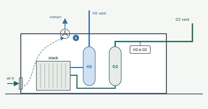
Electrolyser packages are often supplied in containers with forced ventilation, hydrogen detection at roof level and interlocks that shut the electrolyser down if ventilation fails or hydrogen is detected. The ventilation and its monitoring then become part of the area classification: if the zone inside the container relies on forced ventilation, the loss of ventilation must be detected and acted upon (see ventilation in area classification).
Two electrolyser-specific hazards need attention:
- Hydrogen in oxygen. Gas can cross the membrane or diaphragm. The flammable range of hydrogen in oxygen starts at about 4 % vol and extends to about 94 % vol, so the oxygen stream is monitored with a hydrogen-in-oxygen analyser and the electrolyser trips well below the 4 % lower limit.
- Oxygen enrichment. The oxygen outlet and any oxygen leaks create oxygen-enriched air, in which materials ignite more easily and burn more fiercely. Ex equipment is certified for atmospheres with normal oxygen content; an oxygen-enriched zone is a separate hazard that has to be avoided by venting oxygen to a safe place, away from the hydrogen vent and from ignition sources (see oxygen enrichment and inerting).
Worked example: a leak inside a dispenser housing
A dispenser housing has a free volume of about 0.5 m³ (assumed for this example). A fitting inside it starts to leak.
- Hydrogen needed to reach the LEL: 4 % of 0.5 m³ = 0.02 m³ = 20 L of hydrogen at normal conditions.
- Mass: 20 L x 0.084 g/L is about 1.7 g.
- Volume at line pressure: at 70 MPa hydrogen has a density of about 40 g/L, so 1.7 g is only about 42 mL of compressed gas.
If the housing is closed and unventilated, a barely measurable loss of line pressure is enough to make its whole interior flammable. This is why dispenser housings are ventilated or purged, have hydrogen detection at the top, and contain only equipment suitable for the zone.
Selecting Ex equipment
For hydrogen areas, Ex equipment must meet the usual three-part check: EPL for the zone, gas group, and temperature class (see EPL and how to read an Ex marking).
- Gas group: IIC, or IIB+H2 where hydrogen is the only IIC substance. IIB+H2 is common on flameproof enclosures, motors and panels; see IIB+H2 explained.
- Temperature class: T1 is sufficient for hydrogen (autoignition temperature 560 °C in the excodex library; other compilations give roughly 500 to 585 °C, all above the 450 °C limit of T1). Where hydrogen is dispensed next to petrol or diesel on the same forecourt, the fuels' lower ignition temperatures decide; petrol stations commonly require T3. See fuel stations and LPG autogas.
- Non-electrical equipment: compressors, pumps, fans and valves with moving parts in a zone must be assessed for mechanical ignition sources (hot surfaces, friction sparks) to ISO 80079-36 and -37 (Ex h). See non-electrical equipment.
- Static electricity: hydrogen's minimum ignition energy is about 0.017 to 0.02 mJ. Earth and bond all conductive parts, including the vehicle during fuelling, and limit chargeable plastic surfaces (see static electricity).
- Vent stack outlets: hydrogen discharged from vent stacks can ignite, for example by lightning or without an obvious source. Vent stacks are designed so that a fire at the outlet is not dangerous, and ISO 19880-1 contains safety distances for vent stack outlets.
Gas detection
Detection at a hydrogen station has two jobs: to detect leaks early enough to isolate them, and to confirm that enclosures stay below a safe fraction of the LEL. A typical concept:
| Location | Detector type | Typical action |
|---|---|---|
| Top of electrolyser, compressor and dispenser enclosures | point detector: catalytic, thermal conductivity, electrochemical or semiconductor | low alarm: alarm and increase ventilation; high alarm: isolate, depressurise, stop |
| Ventilation extract ducts | point detector | confirm the extract is clean; detect leaks anywhere in the enclosure |
| Under canopies and roofs over dispensers or storage | point detector at the highest point | alarm and emergency shutdown |
| Outdoor high-pressure plant | ultrasonic (acoustic) leak detector | detects the noise of a pressurised leak, independent of wind; used alongside point detectors |
| Enclosures purged with nitrogen | oxygen deficiency detector | protect people entering (see oxygen deficiency) |
Alarm thresholds are typically around 10 % and 20 to 25 % of the LEL (0.4 % and 0.8 to 1 % vol of hydrogen), but they are set as part of the safety concept and must match the response time of the shutdown system. Hydrogen detectors should be calibrated with hydrogen. The relevant standards are ISO 26142 (hydrogen detection apparatus), IEC 60079-29-0 (performance of flammable gas detectors, formerly IEC 60079-29-1) and IEC 60079-29-2 (selection, installation and maintenance). See also where to install gas detectors.
Point detectors outdoors have a basic limitation: a jet or a wind-driven plume may simply miss them. That is why outdoor high-pressure equipment is often covered by ultrasonic detectors and by flame detection in addition to point detectors.
Flame detection
A hydrogen flame contains no carbon, produces no soot and is almost invisible in daylight. It emits strongly in the ultraviolet (OH emission around 306 to 310 nm) and in the infrared water-vapour bands, with its main infrared band around 2.7 µm, but has no carbon dioxide emission at about 4.3 µm. Consequences for a station:
- Use detectors proven for hydrogen fires. UV, UV/IR and multi-spectrum IR detectors designed for hydrogen are used. Detectors that rely on the 4.3 µm CO2 band, typical for hydrocarbon fires, may not respond.
- Cover the likely jet fire locations: compressor and storage enclosures, valve panels, the dispenser island and vent stack outlets. Jet fires from high-pressure leaks are small at the source but can be long, so cone of vision and detection distance for the hydrogen test fire must be checked (see flame detector placement).
- Thermal imaging shows hydrogen flames and is used for fixed monitoring and by responders. A 2026 study by the German national metrology institute detected small burning leaks, practically invisible to the eye, at 40 m in sunlight with both a UV camera and a thermal infrared camera.
- Manage interference: sunlight affects UV imaging, hot surfaces and lamps affect thermal imaging, and arc welding triggers UV detectors. Inhibit flame detection during permitted hot work only through a controlled procedure.
The general principles are covered in detecting hydrogen fires and other invisible flames and how flame detectors work.
Common mistakes
- Copying a petrol station's area classification. Petrol vapour sinks and accumulates low; hydrogen rises or leaves as a jet. Detectors, vents and zone shapes are different.
- Specifying IR gas detectors or standard hydrocarbon IR flame detectors. IR gas detectors cannot see hydrogen, and flame detectors relying on the CO2 band may miss a hydrogen fire.
- Placing point detectors low or in open air only. Installation guidance often quotes positions near the ceiling for lighter gases such as hydrogen, and indoors and under canopies the highest points where it collects are the usual choice, but the right position follows the likely release, the gas behaviour and the airflow (IEC 60079-29-2); outdoors add ultrasonic detection for high-pressure equipment.
- Treating routine venting as a rare event. Purges and depressurisations at start-up, shutdown and every fill are part of normal operation and make vent outlets primary sources of release.
- Forgetting the oxygen side of the electrolyser. Oxygen enrichment is not covered by Ex certification; vent oxygen separately and safely.
- Accepting IIB equipment because the station is "mostly outdoors". Plain IIB is not suitable for hydrogen anywhere in a zone.
Frequently asked questions
What gas group and temperature class are needed at a hydrogen refuelling station?
Equipment in hydrogen hazardous areas must be gas group IIC or IIB+H2. Temperature class T1 is enough for hydrogen alone, but if petrol, diesel or other fuels are handled in the same area, their lower ignition temperatures decide, commonly T3.
Which standard covers hydrogen refuelling stations?
ISO 19880-1 (2020) sets the general requirements for gaseous hydrogen fuelling stations, including hazardous areas, hydrogen detection and safety distances. In Europe, EN 17127 covers outdoor refuelling points and fuelling protocols, and IEC 60079-10-1 and IEC 60079-14 apply to area classification and Ex installation. In North America, NFPA 2 (Hydrogen Technologies Code) is used.
Is the inside of a hydrogen dispenser a hazardous area?
Usually yes, because it contains fittings and valves at high pressure that are secondary sources of release. The zone type depends on the ventilation of the housing and on the release rates; it is determined in the area classification and the equipment inside must suit it.
What gas detectors are used for hydrogen stations?
Catalytic, thermal conductivity, electrochemical and semiconductor point detectors placed at the highest points of enclosures and under canopies, plus ultrasonic leak detectors for outdoor high-pressure plant. Infrared gas detectors cannot detect hydrogen.
What flame detector works for hydrogen fires?
Detectors with documented performance on hydrogen fires: UV, UV/IR and multi-spectrum IR detectors designed for hydrogen, and thermal imaging. Detectors that depend on the carbon dioxide emission band at about 4.3 µm may not detect a hydrogen flame.
Why is hydrogen pre-cooled to -40 °C at the dispenser?
Compressing hydrogen into the vehicle tank heats it, and vehicle tanks are limited to 85 °C. Pre-cooling the gas to about -40 °C allows a 70 MPa fill in a few minutes without exceeding that limit.
Related on excodex
- Hydrogen safety basics: wide flammable range, low ignition energy and invisible flames
- IIB+H2 explained: when is it enough for hydrogen?
- Detecting hydrogen fires and other invisible flames
- Fuel stations and LPG autogas: hazardous areas around dispensers, tanks and vents
- Typical hazardous area examples: tank vents, pumps, compressors and loading points
- Tools: hydrogen in the gas library, Ex marking check, standards spaces IEC 60079-10-1, IEC 60079-14 and IEC 60079-29-2
Standards and further reading
- ISO 19880-1, Gaseous hydrogen, fuelling stations, Part 1: general requirements (2020; ISO lists it as to be revised): iso.org
- ISO 22734-1, Hydrogen generators using water electrolysis, Part 1: safety (2025, replaces ISO 22734:2019): observatory.clean-hydrogen.europa.eu
- EN 17127, Outdoor hydrogen refuelling points dispensing gaseous hydrogen and incorporating filling protocols (2024): evs.ee
- NFPA 2, Hydrogen Technologies Code.
- IEC 60079-10-1 (area classification), IEC 60079-14 (selection and installation), ISO 80079-36 and ISO 80079-37 (non-electrical equipment).
- ISO 26142 (hydrogen detection apparatus), IEC 60079-29-0 and IEC 60079-29-2 (gas detectors).
- US Department of Energy, hydrogen fuelling protocol webinar slides (pressures, pre-cooling, 85 °C tank limit): energy.gov
- Hydrogen Tools (US DOE), tank filling and hydrogen density: h2tools.org
- Brunzendorf (German national metrology institute), Small burning hydrogen leaks in industrial plants: a comparison of UV and IR remote imaging detection, Hydrogen Safety, 2026: reference-global.com
This article is general technical information prepared by the excodex editorial team. It does not replace the applicable standards, the equipment certificates and instructions, national regulations or the assessment of a competent person.