Flame detector placement and cone of vision
Abstract
A flame detector only sees fires inside its cone of vision, large enough for the distance and in direct line of sight. How field of view, the inverse square law, obstructions, coverage mapping and mounting decide where flame detectors go.
A flame detector protects only the space it can see. A fire is detected when three conditions are met: it lies inside the detector's field of view (the cone of vision), it is large enough for its distance, because the radiation reaching the detector falls with the square of the distance, and nothing blocks the line of sight. Placement therefore starts from a defined design fire and the manufacturer's range and field of view data, and checks coverage in three dimensions, usually so that every fire is seen by at least two detectors.
This article explains how cone of vision and range are specified, how fire size changes the detection distance, how obstructions and the environment cut coverage, how coverage mapping works, and how to mount detectors, with a worked example.
Key points
- The field of view is defined by the angle at which the detector still sees the reference fire at 50 % of its on-axis distance. A detector with a 90° field of view sees a fire at 45° off axis only at half the rated distance.
- Detection distance is quoted for a reference fire, most often a 0.3 m × 0.3 m (about 0.1 m², "1 ft²") n-heptane pan. Other fuels and fire sizes give other distances.
- The radiation reaching a detector falls with the square of the distance. To see a fire at twice the distance, it must be about four times larger in area; a fire a quarter of the size is seen at half the distance.
- Detectors cannot see through steel, vessels, walls or glass. Every obstruction casts a shadow, and coverage must be checked from each detector in three dimensions.
- Where an automatic action needs two detectors to agree (two-out-of-N voting), the relevant figure is the area seen by at least two detectors, which is always smaller than the area seen by one.
- Mount detectors high, tilted down, firmly fixed, away from known false alarm sources and where they can be reached for cleaning and testing.
Field of view: the cone of vision
A flame detector is most sensitive along its optical axis and progressively less sensitive towards the edges of its view. Seen from above, the area in which it detects a given fire is a rounded lobe, not a sharp-edged cone.
Performance standards turn this into a number. FM 3260, the US approval standard for radiant energy-sensing fire detectors, asks the manufacturer to state the field of view within which the detector's sensitivity, expressed as detection distance for the test fire, is at least 50 % of the on-axis value. The test checks this in at least four directions: left, right, up and down. EN 54-10, the European standard for point flame detectors, measures the response at different angles of incidence as well.
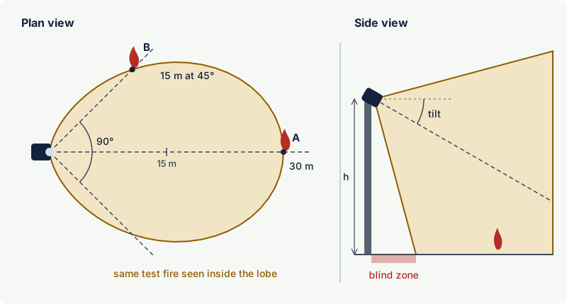
What this means in practice:
- "90° field of view" does not mean full range across 90°. At the edges the range is halved, and many detectors fall off further beyond the stated angle. The manufacturer's polar diagram (sensitivity against angle) is the data to use.
- Horizontal and vertical fields of view can differ. Check both, because a detector looking down onto a process area uses its vertical field of view as much as its horizontal one.
- Fires off the axis need compensation. Where a fire could occur away from the optical axis, NFPA 72 calls for a shorter design distance or additional detectors to make up for the angle, based on the manufacturer's published data.
Horizontal fields of view of industrial point detectors are commonly around 90° to 100°, and some designs are wider, but values and polar shapes vary between designs.
Range and fire size
The reference fire
Detection distances are meaningless without the fire they refer to. The common reference is a pan fire of n-heptane, a clean, repeatable hydrocarbon fuel. FM 3260 uses a 12 in × 12 in (0.3 m × 0.3 m) n-heptane pan, plus an alcohol pan fire and a small propane flame among its test fires (the 2023 ANSI edition adds a JP4/Jet B pan); the manufacturer declares the distance at which the detector reliably alarms. EN 54-10 uses n-heptane and methylated spirit test fires and sorts detectors into response classes by the distance at which they respond.
Manufacturers usually publish a table of distances for other fuels as well, such as methanol, diesel, gas jet fires or hydrogen. For clean-burning fuels such as alcohols, which produce little soot, the stated distance can be considerably shorter than for n-heptane. Use the value for the fuel actually on site, or the most demanding one if several are present.
The inverse square law
The radiant power a detector receives from a small fire is proportional to the radiating area of the flame and inversely proportional to the square of the distance. For the same detector and fuel, the detection distance therefore scales with the square root of the fire area:
d₂ = d₁ × √(A₂ / A₁)
where d₁ is the rated distance for a fire of area A₁. Doubling the distance requires four times the fire area; a quarter of the area halves the distance.
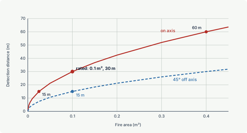
The relation is an approximation with clear limits:
- Long distances. CO2 and water vapour in the air absorb part of the radiation in the IR bands. Over long paths, and in humid air, the real range falls below the square-root curve. Never extrapolate beyond the maximum distance in the manufacturer's data.
- Very small fires. Small flames radiate less and flicker differently, so the curve should not be used far below the rated fire size.
- Large or close fires. When the flame is large compared with the distance, the point-source assumption no longer applies. This rarely limits detection, since a large close fire gives a strong signal.
- Sensitivity settings. The rated distance applies at a stated sensitivity setting. Selecting a lower sensitivity to cure nuisance alarms shortens every distance in the layout.
Choosing the design fire
The design fire is the smallest fire that must be detected in a given area. It comes from the fire hazard analysis: a small pool fire at a pump, a gas jet fire at a compressor, a fire at a loading arm. Some approaches express it as a flame size, others as a radiant heat output in kilowatts; mapping guidance and some offshore codes define design fires and the number of detectors that must see them. The smaller the design fire, the more detectors are needed: with half the distance, each detector covers roughly a quarter of the floor area.
Obstructions, shadows and the environment
Flame detectors need direct line of sight. Steel structures, vessels, pipe racks, cable trays, equipment housings and walls all cast shadows in which a fire is invisible to that detector. A fire behind a vessel on the far side of a skid can burn undetected until it grows beyond the shadow.
Less obvious obstructions:
- Glass and transparent panels. Ordinary glass absorbs the UV band of flame detectors and much of the infrared beyond about 3 µm. A detector behind a window, or a fire behind a glass partition, is effectively blocked.
- Gratings and open floors. Grating partly blocks the view, depending on the viewing angle. Fires below a grated deck usually need detectors on that level.
- Smoke. Indoors, smoke collects under the roof. UV detectors in particular lose signal in smoke and are better mounted below the expected smoke layer; IR detectors tolerate smoke better.
- Weather and process conditions. Heavy rain, fog, snow, steam and spray attenuate the IR bands; oil mist and dirt coat windows. Detectors should not be placed where deluge water, washdown or process spray will hit the window.
The cure for shadows is geometry: detectors looking from different directions, so that the shadow of one is covered by another. This is the main reason why process areas are normally covered by several detectors from different corners rather than one detector looking down the middle.
Fire detection mapping
Fire detector mapping (also called fire and gas mapping) is a systematic check of what the detectors can see. Guidance such as the ISA technical report ISA-TR84.00.07 (first published in 2010, current edition 2026) distinguishes two measures:
- Geographic coverage: the fraction of the area, at a given elevation, in which a design fire would be detected. It depends on detector positions, performance and obstructions.
- Scenario coverage: the fraction of realistic fire scenarios that would be detected, weighted by where and how often they can occur. It is more informative but needs more input data.
A typical mapping study proceeds as follows:
- Define the monitored zones, their boundaries and the heights of interest (usually grade, plus elevated decks).
- Define the design fire for each zone and the detection required (one detector, or two for voted executive action).
- Build a three-dimensional model of the area including major obstructions.
- Enter each detector's position, aim, field of view and range for the design fire from the manufacturer's data.
- Calculate, for a grid of points, how many detectors see a fire there, and report coverage by one and by at least two detectors.
- Move, re-aim or add detectors until the coverage targets set by the risk assessment are met.
Specialised software does the ray tracing, but the results are only as good as the inputs: realistic design fires, correct detector data for the fuel, and an up-to-date model of the plant. Mapping should be repeated when equipment is added or moved.
Note: Coverage targets are not universal numbers. They come from the site's hazard and risk assessment, and in a performance-based design they are linked to the required risk reduction of the fire and gas function (see gas detection and functional safety).
Worked example: a 20 m × 12 m pump bay
A pump bay of 20 m × 12 m contains a vertical vessel and a pump skid. The design fire is a 0.1 m² hydrocarbon pool fire. The detectors chosen are rated (illustrative values) at 30 m on axis for a 0.1 m² n-heptane pan, with a 90° field of view. For the calculation their detection distance is assumed to fall smoothly with the angle off axis (in proportion to cos²), to 50 % at 45° and further beyond; a real design uses the manufacturer's polar diagram. Detectors are mounted at 6 m.
Layout A: two detectors in opposite corners, both aimed at the centre of the floor.
- Far corner from each detector: slant distance about 24 m, about 13° off axis. Range at that angle is about 28.5 m, so the corner is covered.
- Corner at the end of each detector's short wall: about 13 m from the near detector but 52° off axis, beyond the edge of its field of view, where its range has fallen to about 11 m. The opposite detector sees it at about 21 m and 30° off axis, where its range is about 22 m: covered, but only just, and by one detector only.
A grid calculation over the floor gives the result shown on the left of the figure: every point is seen by at least one detector, but only 59 % of the floor is seen by two.
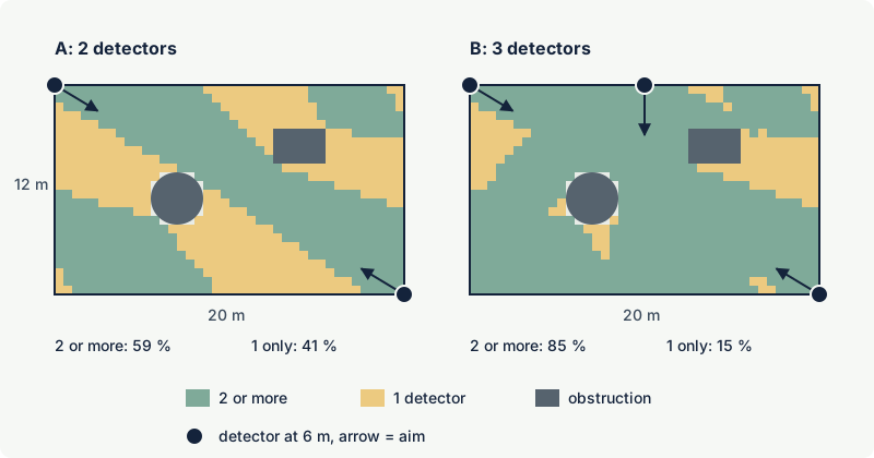
If the fire and gas logic releases deluge only when two detectors confirm a fire, 41 % of the floor would rely on a single detector alarm and operator action. Layout B adds a third detector at the middle of one long wall, aimed across the bay; coverage by two or more detectors rises to 85 %.
The design fire matters as much as the layout. Repeating the calculation for a fire one quarter of the size (0.025 m²), which halves every distance, layout A leaves about a third of the floor seen by no detector at all and only about 6 % seen by two.
Mounting and installation
- Height and tilt. Mount high enough to look over obstructions and down onto the hazard, with a downward tilt. Tilting down keeps the sky and horizon out of view and stops water and dirt collecting on the window. Remember the blind zone directly below the detector and cover it from another position if fires can occur there.
- Firm mounting. Use a rigid bracket and lock the swivel mount after aiming. Vibration can shift the aim, and a vibrating detector viewing a hot surface sees a modulated signal that can resemble flicker.
- Aim with care. Use the manufacturer's alignment aid where one is available, and record the final aim on the layout drawing so that it can be checked after maintenance.
- Keep false alarm sources out of view. Flares, hot exhausts, welding bays, reflective water or roof surfaces and direct sunlight should not be in the field of view (see false alarms in flame detectors).
- Access. Detectors need periodic window cleaning and functional testing with a test lamp or test fire. Choose positions that can be reached safely, or provide platforms.
- Ex requirements. In a hazardous area the detector and its cable entries must suit the zone, gas group and temperature class and be installed according to IEC 60079-14.
Common mistakes
- Using the on-axis range across the whole field of view. At the edge of a 90° field of view the range is typically half the on-axis value. Use the polar data.
- Quoting a range without the fire. "Detects at 60 m" means nothing until the fuel, fire size and sensitivity setting are stated. Compare detectors on the same reference fire.
- Ignoring the third dimension. A layout that looks complete on a plan drawing can have large shadows behind vessels and under decks. Check from each detector's position in 3D.
- Counting single-detector coverage where the logic needs two. If executive action is voted, report coverage by two or more detectors.
- Reducing sensitivity or adding long delays after nuisance alarms without re-mapping. Lower sensitivity shrinks every detector's range and can open gaps.
- Not re-mapping after plant changes. A new skid, enclosure or scaffold can block a detector's view permanently or temporarily.
Frequently asked questions
What is the cone of vision of a flame detector?
It is the field of view within which the detector sees a reference fire at no less than half of its on-axis distance. A detector with a 90° cone of vision detects the rated fire at full distance straight ahead and at half that distance 45° to either side.
How far can a flame detector see?
It depends on the fire. Ranges are stated for a reference fire, usually a 0.1 m² n-heptane pan, and multi-spectrum IR detectors reach several tens of metres for that fire. Smaller fires, other fuels, off-axis positions and lower sensitivity settings all reduce the distance.
Why does doubling the distance need a four times bigger fire?
The radiation from a fire spreads out over an area that grows with the square of the distance, so the power reaching the detector falls with the distance squared. To keep the same signal at twice the distance, the flame must radiate four times as much, roughly four times its area.
How many flame detectors do I need for an area?
There is no fixed number. It follows from the design fire, the detector's range and field of view for that fire, the obstructions and whether one or two detectors must confirm a fire. Coverage mapping shows whether the targets from the risk assessment are met.
Should flame detectors point downwards?
Yes, in most cases. A downward tilt lets the detector see the floor area where pool fires and leaks occur, keeps the sky and sun out of view and reduces water and dirt on the window. Follow the manufacturer's minimum tilt and check that the blind zone below the detector is covered.
Can a flame detector see through glass?
Generally no. Ordinary glass absorbs the ultraviolet band used by UV detectors and much of the infrared used by IR detectors. Detectors must view the hazard directly, and their own window is made of a special material transparent in their bands.
Related on excodex
- How flame detectors work: UV, IR, UV/IR and multi-spectrum IR
- False alarms in flame detectors: common sources and how to avoid them
- Flame detector performance standards: EN 54-10, FM 3260 and response time
- Open path gas detectors: line-of-sight detection for large areas
- Gas detection and functional safety: SIL for gas detection systems
- Standards spaces IEC 60079-14 and IEC 61511; questions in the forum
Standards and further reading
- FM 3260, examination (approval) standard for radiant energy-sensing fire detectors (October 2021 edition), including test fires, the 30 second response limit and the 50 % field of view definition: https://www.fmapprovals.com/-/media/Feature/Approval-Standards/3260-pdf.pdf
- ANSI/FM 3260-2023, the American National Standard version, approved on 24 August 2023; its test fires add a JP4/Jet B pan fire: https://www.fmapprovals.com/-/media/Feature/Approval-Standards/3260ansi-pdf.pdf
- EN 54-10:2002 with amendment A1:2005, flame detectors (point detectors) for fire detection and fire alarm systems in buildings; still the current edition, because a 2012 revision draft was abandoned at enquiry stage.
- NFPA 72, National Fire Alarm and Signaling Code, requirements for radiant energy-sensing detectors, including compensation for fires off the optical axis.
- ISA-TR84.00.07 (current edition 2026), guidance on the evaluation of fire and gas system effectiveness, including geographic and scenario coverage.
- IEC 61511, functional safety for the process industry, where fire detection forms part of a safety instrumented function.
- IEC 60079-14, design, selection and erection of electrical installations in explosive atmospheres.
This article is general technical information prepared by the excodex editorial team. It does not replace the applicable standards, the equipment certificates and instructions, national regulations or the assessment of a competent person.