Non-electrical equipment in hazardous areas: Ex h, constructional safety c, control of ignition sources b and liquid immersion k
Abstract
Pumps, gearboxes, fans and couplings can ignite gas or dust through friction, sparks and hot surfaces. How ISO 80079-36 and -37 assess and protect them (types c, b and k), what the Ex h marking means and how ATEX applies.
A pump, gearbox, fan, coupling or brake has no wiring to spark, but it can still ignite an explosive atmosphere through frictional heat, mechanical sparks, static electricity or hot process fluid. Such non-electrical equipment is designed and assessed to ISO 80079-36, which requires an ignition hazard assessment of every possible ignition source, and protected where needed by the types of protection in ISO 80079-37: constructional safety "c", control of ignition sources "b" and liquid immersion "k". Whatever measures are used, the equipment is marked Ex h, followed by gas or dust group, temperature class and EPL, for example Ex h IIB T4 Gb.
This article explains when mechanical equipment falls under ATEX, how the ignition hazard assessment works, the typical mechanical ignition sources, what c, b and k mean in practice, how to read an Ex h marking, and what this means for pumps, gearboxes and fans.
Key points
- Non-electrical equipment needs explosion protection when it has its own potential ignition source, typically moving parts that can create hot surfaces or friction sparks. Hand tools and manually operated equipment without stored energy are outside ISO 80079-36, and the European Commission's ATEX guidelines list hand-operated valves as out of scope.
- ISO 80079-36:2016 (basic method) and ISO 80079-37:2016 (types c, b, k) replaced the European EN 13463 series; the co-existence period for EN 13463-1 under ATEX ended on 31 October 2019. Both ISO standards are being revised (committee drafts registered in 2025).
- The EPL follows from the assessment: no effective ignition source in normal operation gives Gc or Dc; also none in expected malfunctions gives Gb or Db; also none in rare malfunctions gives Ga or Da.
- The marking uses the single letter
hwith no level letter. The types c, b and k do not appear in the marking; they are recorded in the documentation. - Under ATEX, category 2 non-electrical equipment follows internal production control plus lodging the technical documentation with a notified body, while category 2 electrical equipment and internal combustion engines need EU-type examination.
- Where the surface temperature depends on the process (a pump heated by hot liquid), the marking can show a temperature range such as
T6…T4, and the instructions link each class to the process conditions.
When does mechanical equipment fall under ATEX?
Directive 2014/34/EU covers equipment intended for use in potentially explosive atmospheres that has its own potential source of ignition. For electrical equipment that is almost always the case. For mechanical equipment it depends on what moves, how fast, with how much energy, and what can go wrong.
The European Commission's ATEX guidelines (6th edition, January 2026) name gears, fans, pumps, compressors, mixers and brakes as typical non-electrical equipment with potential ignition sources, from hot surfaces or friction sparks. Their table of examples puts mechanical gears, mechanical brakes, rotary valves and non-electrical fans driven by air motors inside the scope, and hand-operated valves outside it. Equipment that moves very slowly or has very low power input may be unable to create an ignition source even in a rare malfunction; it is then not ATEX equipment and is not marked as such.
Static process equipment without its own energy source, such as tanks, vessels and fixed pipework, is outside ISO 80079-36 and is dealt with by the plant's risk assessment and area classification.
The standards: ISO 80079-36 and ISO 80079-37
| Standard | Content |
|---|---|
| ISO 80079-36:2016 | Basic method and requirements: scope, ignition hazard assessment, requirements for each ignition source, temperature determination, instructions and marking. Supplements and modifies IEC 60079-0. |
| ISO 80079-37:2016 | Three non-electrical types of protection: constructional safety "c", control of ignition source "b", liquid immersion "k". |
| IEC 60079-1, -2, -31 | Flameproof "d", pressurisation "p" and dust protection by enclosure "t" may also be applied to non-electrical equipment, taking account of its mechanical ignition sources. |
The general requirements of IEC 60079-0 still apply unless ISO 80079-36 modifies them. The standard applies to the same range of atmospheric conditions as the electrical standards (temperatures of -20 °C to +60 °C, 80 kPa to 110 kPa, normal air; this is the scope of the standards, not an equipment rating) and the same normal ambient range of -20 °C to +40 °C unless another range is marked.
The ignition hazard assessment
The core of ISO 80079-36 is a structured assessment that narrows a long list of possible ignition sources down to the ones that must be controlled.
- Possible ignition sources. Start from the full list: hot surfaces; flames and hot gases; mechanically generated sparks; electrical sources; stray currents and cathodic protection; static electricity; lightning; radio frequency waves; optical radiation; ionising radiation; ultrasonics; adiabatic compression and shock waves; exothermic reactions including self-ignition of dust. See ignition sources in hazardous areas.
- Equipment-related sources. Keep those the equipment itself could cause, regardless of whether they are strong enough to ignite anything. A machine with a bearing has frictional heat as an equipment-related source.
- Potential sources. Keep those that are capable of igniting the atmosphere in question.
- Effective sources. Decide when each potential source occurs: in normal operation, in an expected malfunction, or in a rare malfunction. That timing, compared with the intended EPL, decides whether a protective measure is needed.
- Measures and documentation. Apply measures (design, type c, b or k, or an electrical type such as d, p or t) until no effective ignition source remains for the intended EPL, and record the reasoning, the measures and any instructions the user must follow.
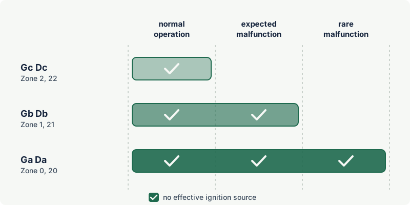
| EPL | Must have no effective ignition source during | Typical use |
|---|---|---|
| Gc, Dc | Normal operation | Zone 2, Zone 22 |
| Gb, Db | Normal operation and expected malfunctions | Zone 1, Zone 21 |
| Ga, Da | Normal operation, expected and rare malfunctions | Zone 0, Zone 20 |
For EPL Ga or Da, if no single type of protection is enough, the guidance in ISO 80079-36 is to apply two independent types, each suitable for Gb or Db. Equipment built to recognised industrial standards whose assessment finds no effective source in normal operation can be classified Gc or Dc without further measures. The standard notes that compliance with those industrial standards does not have to be verified by a third party.
Mechanical ignition sources in practice
| Source | Where it arises | Typical measures |
|---|---|---|
| Hot surfaces from friction | Bearings, mechanical seals, stuffing boxes, slipping belts and clutches, brakes, rubbing impellers | Bearing selection and life, lubrication, clearances, temperature monitoring, dry-running protection |
| Mechanically generated sparks | Impact or rubbing of metal parts, foreign objects in a fan or mixer, failed bearing cage | Clearances, guards, material pairing, sacrificial or non-sparking parts |
| Light metals | Aluminium, magnesium or titanium struck by rusty steel (thermite sparks) | Restrict light metals on external parts and on parts that can rub or be struck |
| Static electricity | Drive belts, plastic fan blades, non-conductive linings, fast-moving films and powders | Conductive or antistatic materials, earthing and bonding |
| Adiabatic compression | Compressors, pneumatic systems, rapid valve closure | Limit compression ratios and temperatures, design of valves and pipework |
| Hot process medium | Pumps and agitators handling hot liquids | Temperature class linked to process temperature in the instructions |
Numbers worth knowing
ISO 80079-36 gives a few useful thresholds, paraphrased here:
- Friction speed. A relative contact speed of 1 m/s is often used as the limit below which friction does not ignite an explosive atmosphere. The standard warns of exceptions: very ignition-sensitive dusts such as sulphur, and gases such as hydrogen and ethylene under high contact load; acetylene, carbon disulphide, carbon monoxide and ethylene oxide are also likely to be ignited.
- Single impacts. Impacts between metal parts need not be treated as potential ignition sources if the impact velocity is below 1 m/s and the potential impact energy below 500 J, provided certain material pairings are avoided (light metals against rusty or ferritic steel, hard steel against hard steel or granite). With combinations of non-sparking metals, the limits are 15 m/s and 60 J for gas atmospheres (125 J for dust).
- Lubricants and coolants that are needed for protection must have an autoignition temperature at least 50 K above the maximum surface temperature where they are used (ISO 80079-37).
Types of protection c, b and k
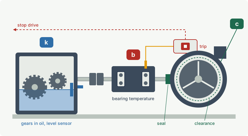
Constructional safety "c"
Constructional safety means designing out the ignition risk: the equipment is built so that hot surfaces, sparks and adiabatic compression from moving parts are unlikely to occur for the intended EPL. ISO 80079-37 sets requirements for ingress protection where foreign bodies or dust could cause a malfunction (for example at least IP5X and IPX4 in gas atmospheres when entry of dust or liquids could lead to an ignition source), seals and packed glands, lubrication, vibration, clearances between moving and fixed parts, bearings (including rated life, fit, alignment, lubrication and protection from stray currents), gear, belt and chain drives, clutches, couplings, brakes and conveyor belts.
Constructional safety depends heavily on correct installation and maintenance: alignment, lubrication intervals and bearing replacement become part of the explosion protection and appear in the instructions.
Control of ignition source "b"
Here sensors detect conditions that would lead to an ignition source, and a control measure stops it from becoming effective: a temperature sensor on a bearing, a level sensor for oil or for the pumped liquid, a speed sensor against overspeed, a vibration sensor. The action can be automatic (shutdown) or manual (an alarm to which an operator responds), within limits set by the standard. ISO 80079-37 defines two ignition protection types, b1 and b2, with different reliability requirements, and tabulates which one is needed for each EPL; functional safety standards such as IEC 61508 or ISO 13849-1 can be used to show the reliability of the devices.
Type b typically protects a pump against dry running or a gearbox against a failing bearing when design alone cannot cover the expected malfunctions.
Liquid immersion "k"
Potential ignition sources are made ineffective by immersing them in a protective liquid, or by keeping their active surfaces continuously wetted. Examples are gears running in an oil bath and submerged or liquid-filled pump parts. The standard covers sealed enclosures, vented enclosures and open equipment, working angles (so the parts stay immersed when tilted), level monitoring and loss of liquid.
Temperature class and the Ex h marking
Maximum surface temperature
The maximum surface temperature is determined at the worst operating conditions the manufacturer allows, including expected malfunctions for Gb or Db and rare malfunctions for Ga or Da. When temperatures are type tested for Gb or Gc equipment, the measured value must stay 5 K below the class limit for T6 to T3 and 10 K below for T2 and T1. For Ga equipment the margin is larger: the measured temperature may not exceed 80 % of the marked value, because rare mechanical malfunctions are hard to reproduce in a test.
When the surface temperature depends mainly on the process, such as a pump handling hot liquid, the manufacturer cannot give a single class. The marking then shows a range, for example T6…T4 or 85 °C…150 °C, and the instructions tie each class to process conditions. See temperature classes.
Reading the marking
ISO 80079-36 marking contains the manufacturer and type, Ex, the letter h, the group (with subdivision), the temperature class or maximum surface temperature, the EPL, the ambient range if it is not -20 °C to +40 °C (IEC 60079-0 edition 8, 2026, now requires the rated ambient range on every Ex marking, so expect it to appear on more labels), the serial number and the certificate reference with X if specific conditions apply.
| Marking | Meaning |
|---|---|
Ex h IIB T4 Gb | Non-electrical equipment for IIB gases, max surface temperature 135 °C, EPL Gb (Zone 1) |
Ex h IIIC T120°C Db | For dust group IIIC, max surface temperature 120 °C, EPL Db (Zone 21) |
II 2 G Ex h IIC T4…T1 Gb | ATEX category 2 gas; temperature class depends on process conditions given in the instructions |
Ex db h IIA T4 Gb | Equipment with a flameproof electrical part and a non-electrical part certified together |
II 2 G c T4 | Older EN 13463 style, with the type symbol shown directly |
No level letter follows h; the EPL at the end carries the protection level. And the letters c, b and k do not appear in the current marking, so an Ex h label does not tell you whether the equipment relies on design, on sensors or on an oil bath. The instructions do, and they matter for maintenance: a type b machine is only protected while its sensors and shutdown work. Combined electrical and non-electrical markings are explained in combined protection concepts.
ATEX for pumps, gearboxes and fans
Conformity assessment
Article 13 of Directive 2014/34/EU sets different routes for electrical and non-electrical equipment:
| Category | Electrical equipment and internal combustion engines | Other (non-electrical) equipment |
|---|---|---|
| 1 and M1 | EU-type examination plus production quality assurance or product verification | Same as electrical |
| 2 and M2 | EU-type examination plus internal production control with supervised product testing, or product quality assurance | Internal production control, with the technical documentation communicated to a notified body, which acknowledges receipt and retains it |
| 3 | Internal production control | Internal production control |
Unit verification is available for any category. For category 2 non-electrical equipment the notified body keeps the file but does not examine the product, so no notified body number follows the CE marking on that basis. Voluntary third-party assessment, or certification under the IECEx scheme, is also possible.
Pump and motor: one product or an assembly?
A pump driven by an electric motor is usually two pieces of equipment. The guidelines describe a product formed by combining certified equipment into a functional unit as an assembly: whoever places it on the market as a unit becomes its manufacturer and must assess the additional ignition hazards created by the combination, such as the coupling, guard and baseplate, and alignment. Mechanical equipment fitted only with "simple apparatus" such as a thermocouple follows the non-electrical procedure.
The inside of a pump can also be a different zone from its surroundings. The guidelines give the example of a petrol vapour recovery pump: its inlet and outlet connect to a zone 0 atmosphere, so the parts in contact with it must meet category 1, while the outer body in zone 1 meets category 2, and both categories appear in the marking.
Practical points by equipment type
- Pumps. Typical ignition sources are dry-running mechanical seals, bearing failure, impeller rubbing, cavitation and running against a closed valve (the liquid heats up). Measures include seal flushing and quench systems, dry-running and temperature protection (type b), and instructions that tie the temperature class to the liquid temperature. The pumped liquid often cools and lubricates the pump, so priming requirements are part of the protection.
- Gearboxes. Hot spots come from bearings, gear meshing and loss of oil. Oil-bath lubrication (type k), oil level and temperature monitoring (type b), and bearing life calculations (type c) are typical.
- Fans. The main risk is the impeller touching the casing or inlet, through imbalance, bearing failure or foreign objects, with the material pairing deciding how incendive the contact is. Clearances, material choice, conductive materials against static and vibration monitoring are typical. The European standard EN 14986 covers the design of fans for potentially explosive atmospheres.
- Couplings, belts and brakes. Slip and friction heat, static on belts, and sparks from failing parts; antistatic belts, alignment and guard materials matter.
Practical case: a centrifugal pump for hot solvent in Zone 1
A plant pumps toluene (gas group IIA, autoignition temperature 530 °C, T1) at up to 90 °C in a Zone 1 area. The pump offered is marked II 2 G Ex h IIB T4…T1 Gb with a certificate number ending in X, and is driven by an Ex db eb IIB T4 Gb motor. The pump instructions (manufacturer's data, illustrative only) give T4 for liquid temperatures up to 100 °C, provided the dry-running protection supplied is connected and the seal flush plan is in operation.
- Group and EPL. IIB covers IIA; Gb suits Zone 1. Pass.
- Temperature. At 90 °C liquid the pump is T4 (135 °C). Toluene needs only T1. Pass, with margin even for upset conditions.
- Conditions behind the X. The T4 rating depends on the dry-running protection and the flush plan. Both are protective measures, so they go into the plant's equipment list, inspection plan and trip testing.
- Assembly. Pump, motor, coupling and guard are supplied on one baseplate. The supplier confirms that the combination has been assessed (coupling guard material, alignment, earthing of the baseplate and of the pump against static).
- Operation. Running against a closed discharge valve or with the suction blocked would heat the liquid and the casing beyond the conditions assessed. The operating procedure and the minimum-flow protection cover this.
Common mistakes
- "It has no electrics, so ATEX doesn't apply." Pumps, gearboxes, fans, brakes, couplings and mixers with their own potential ignition sources are in scope and need an ignition hazard assessment.
- Treating the motor's marking as the pump's marking. A certified motor does not make the pump, coupling or gearbox suitable. Each needs its own marking, and the combination needs an assembly assessment.
- Ignoring the protective measures after commissioning. A type b pump is protected only while its temperature, level or dry-running sensors and their shutdown work. Include them in testing and inspection.
- Reading
Ex has a single protection method. The marking hides whether c, b or k is used. Read the instructions to know what keeps the equipment safe. - Overlooking process heat. A pump marked with a temperature range is T4 only under the process conditions the instructions specify. Check the hottest credible liquid temperature, including upsets.
- Replacing parts with "equivalent" ones. A different seal, bearing, belt or impeller material can change the ignition hazard assessment, for example an aluminium part where steel was assessed.
Frequently asked questions
What does Ex h mean?
Ex h marks non-electrical equipment built to ISO 80079-36 and protected by the measures of ISO 80079-37 (constructional safety c, control of ignition source b, liquid immersion k) or by d, p or t applied to non-electrical equipment. The letter h has no level letter; the EPL at the end of the string gives the level of protection.
Do pumps need ATEX certification?
A pump intended for use in a potentially explosive atmosphere, or connected to one, falls under Directive 2014/34/EU if it has its own potential ignition source, which most powered pumps do. For category 2 the manufacturer follows internal production control and lodges the technical file with a notified body; for category 1 an EU-type examination is required.
What replaced EN 13463?
The EN 13463 series for non-electrical equipment was replaced by EN ISO 80079-36 (basic method) and EN ISO 80079-37 (types c, b and k). Under ATEX the co-existence period for EN 13463-1 ended on 31 October 2019. Equipment certified earlier may still show old-style markings with the type letters.
What is the difference between constructional safety c and control of ignition source b?
Constructional safety relies on design: correct bearings, clearances, seals, materials and lubrication make ignition sources unlikely. Control of ignition source adds sensors and actions, such as a bearing temperature sensor that stops the machine before the surface becomes too hot. Many machines use both.
Is a manual valve ATEX equipment?
Generally not. Hand-operated valves without their own energy source are listed by the European Commission's ATEX guidelines as outside the scope, and ISO 80079-36 excludes hand tools and manually operated equipment without energy storage. Actuated valves can be in scope because of the actuator.
Related on excodex
- Ignition sources in hazardous areas: the 13 ignition sources and how to control them
- Ex protection concepts at a glance
- Combined protection concepts: Ex db eb and multiple markings
- ATEX equipment categories 1, 2 and 3
- Static electricity as an ignition source
- Tools and spaces: Ex marking check, standards spaces ISO 80079-36, ISO 80079-37, ATEX 2014/34/EU, EN 1127-1, forum
Standards and further reading
- ISO 80079-36, non-electrical equipment for explosive atmospheres: basic method and requirements (edition 1, 2016, with 2019 corrigendum; under revision).
- ISO 80079-37, non-electrical type of protection constructional safety "c", control of ignition source "b", liquid immersion "k" (edition 1, 2016; under revision).
- IEC 60079-0, general requirements; IEC 60079-1, -2 and -31 where d, p or t are applied.
- EN 1127-1, explosion prevention and protection: basic concepts and methodology.
- EN 14986, design of fans working in potentially explosive atmospheres.
- IEC webstore, ISO 80079-36:2016 scope summary: webstore.iec.ch
- ISO 80079-37:2016 preview with scope and definitions: cdn.standards.iteh.ai
- Directive 2014/34/EU, Article 13 (conformity assessment procedures): legislation.gov.uk
- European Commission, ATEX 2014/34/EU Guidelines, 6th edition (January 2026), sections on non-electrical equipment and assemblies: single-market-economy.ec.europa.eu
- IEC 60079-0:2011 interpretation sheet 3 (2018) on combined electrical and non-electrical marking: iecex.com
This article is general technical information prepared by the excodex editorial team. It does not replace the applicable standards, the equipment certificates and instructions, national regulations or the assessment of a competent person.