Ignition sources in hazardous areas: the 13 ignition sources and how to control them
Abstract
EN 1127-1 lists 13 types of ignition source, from hot surfaces and sparks to static, lightning, radio waves, ultrasound and exothermic reactions. How each one ignites an explosive atmosphere and the practical controls used in Ex areas.
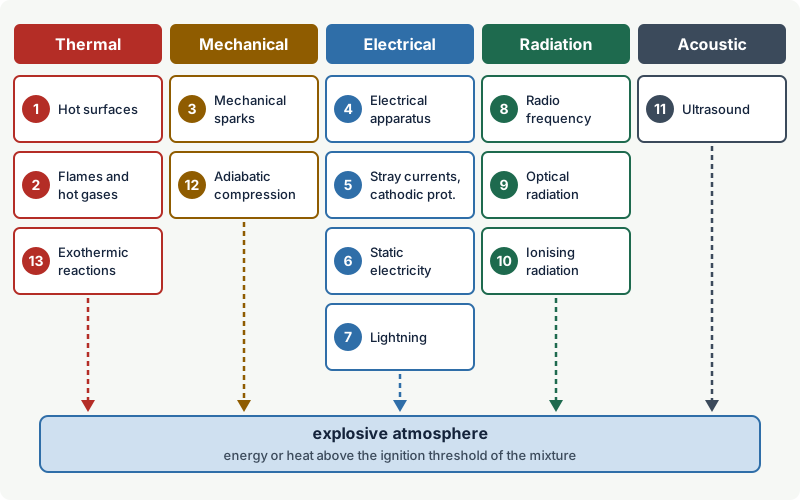
An ignition source is anything that can deliver enough energy or heat to start a self-sustaining flame in an explosive atmosphere. The European basic standard EN 1127-1 lists 13 types: hot surfaces; flames and hot gases; mechanically generated sparks; electrical apparatus; stray currents and cathodic protection; static electricity; lightning; radio-frequency waves; optical radiation; ionising radiation; ultrasound; adiabatic compression and shock waves; and exothermic reactions. In a hazardous area every one of them has to be identified and either excluded or made ineffective, to a degree that depends on the zone.
This article explains how each source ignites a gas, vapour or dust atmosphere, the controls that work in practice, and how the zone decides how far ignition sources must be avoided.
Key points
- EN 1127-1 (current edition 2019) names 13 types of ignition source; ISO 80079-36 uses the same list for the ignition hazard assessment of non-electrical equipment.
- An ignition source is only relevant if it is effective: it must deliver enough energy, temperature or power to the specific mixture, which is why gas group, temperature class and minimum ignition energy matter.
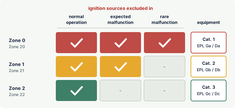
- The zone sets the depth of protection: in Zone 2 or 22 ignition sources must be excluded in normal operation, in Zone 1 or 21 also during expected malfunctions, and in Zone 0 or 20 even during rare malfunctions.
- If the likelihood of an ignition source cannot be estimated, EN 1127-1 requires it to be assumed present at all times.
- Hot work, hot surfaces, friction and impact, electrical faults and static electricity are the sources met most often in plant assessments; the rarer ones, such as radiation and ultrasound, still have to be checked and recorded.
- Ex-certified electrical equipment controls only one of the 13 sources. Pumps, fans, couplings, process heat, tools, people and the process chemistry need their own controls.
Where the list of 13 comes from
The idea of a fixed checklist of ignition sources comes from EN 1127-1, the European standard on basic concepts and methodology for explosion prevention and protection. Its current edition was approved by CEN in June 2019 and replaced the 2011 edition. It sits under both ATEX directives: the equipment directive 2014/34/EU requires manufacturers to take into account the nature of "every electrical and non-electrical source of ignition", and the workplace directive 1999/92/EC requires employers to assess the likelihood that ignition sources, including electrostatic discharges, will be present and become active.
ISO 80079-36:2016 (non-electrical equipment, basic method and requirements) uses the same family of sources for its ignition hazard assessment, the systematic analysis behind every Ex h marking. A revision of ISO 80079-36 is in preparation. ISO 80079-37 then describes the non-electrical protection types that answer the hazards found: constructional safety c, control of ignition sources b and liquid immersion k.
What makes an ignition source effective
An explosive atmosphere ignites when a small volume of it is heated fast enough, and to a high enough temperature, for the reaction to become self-sustaining. Every ignition source is a different way of doing this, and every substance has its own sensitivity:
- Temperature sensitivity is described by the autoignition temperature (AIT) for gases and vapours, and by the minimum ignition temperature of a cloud and of a layer for dusts. It governs hot surfaces and is expressed in equipment by the temperature class (T1 to T6) or a maximum surface temperature in °C.
- Energy sensitivity is described by the minimum ignition energy (MIE), the smallest capacitive spark that ignites the most easily ignited mixture. It governs sparks and static discharges. Most hydrocarbon vapours lie at a few tenths of a millijoule; hydrogen, acetylene and carbon disulphide are about ten times more sensitive. See flash point, autoignition temperature and minimum ignition energy.
- Flame transmission is described by the maximum experimental safe gap (MESG), which sets the gas group IIA, IIB or IIC.
The spread is large. Carbon disulfide autoignites at 90 °C and diethyl ether at 175 °C, while methane needs about 600 °C (excodex gas library values). A steam pipe that is harmless in a natural gas compressor house can ignite ether vapour in a pharmaceutical plant, so an ignition source is only ever assessed against the substances that can be present.
The 13 ignition sources and their controls
The table gives the overview; the sections below explain each source.
| No. | Ignition source | Typical examples | Main controls |
|---|---|---|---|
| 1 | Hot surfaces | Motors, bearings, steam and thermal oil lines, exhausts, heaters, dryers | T-class or maximum surface temperature below the ignition temperature, insulation, temperature monitoring |
| 2 | Flames and hot gases (including hot particles) | Hot work, burners, flares, engine exhausts, smoking, welding beads | Permit to work, gas testing, flame arresters, spark arresters, keeping fired equipment outside zones |
| 3 | Mechanically generated sparks | Grinding, impacts, rubbing fan blades, failed bearings, tramp metal in mills | Non-sparking material pairs, clearances, condition monitoring, magnets and separators, tool rules |
| 4 | Electrical apparatus | Switch contacts, loose terminals, faulty cables, lamps, ordinary electronics | Ex equipment of the right EPL, gas group and T-class, correct installation and inspection |
| 5 | Stray currents and cathodic protection | Return currents of welding and railways, fault currents, cathodic protection systems | Bonding, bridging before breaking pipework, insulating joints with controlled spark gaps |
| 6 | Static electricity | Liquid flow and filtration, powder transfer, insulating plastics, people | Earthing and bonding, conductivity control, velocity limits, dissipative materials and footwear |
| 7 | Lightning | Direct strikes, induced voltages, rim-seal fires on floating-roof tanks | Lightning protection system, equipotential bonding, surge protection |
| 8 | Radio-frequency waves (10⁴ to 3 × 10¹¹ Hz) | Transmitters, radar, induction heating, RF dryers | Distance and power limits, assessment of metal structures acting as receiving antennas |
| 9 | Optical radiation (3 × 10¹¹ to 3 × 10¹⁵ Hz) | Lasers, fibre optics, focused sunlight, high-power lamps | IEC 60079-28 protection types, beam enclosure, power limits |
| 10 | Ionising radiation | X-ray equipment, radioactive level and density gauges | Limiting absorbed energy, assessment of sources and absorbers |
| 11 | Ultrasound | Ultrasonic cleaning, sonochemistry, high-power transducers | Limiting sound intensity, avoiding absorbers at hot spots, assessment of liquids |
| 12 | Adiabatic compression and shock waves | Compressors, rapid valve opening, gas released into closed pipes | Limiting compression ratio and temperature, slow opening, design to avoid shock focusing |
| 13 | Exothermic reactions, including self-ignition of dusts | Pyrophoric iron sulphide, oily rags, smouldering dust layers, reactive chemicals | Process control, housekeeping, inerting, avoiding storage that traps heat |
1. Hot surfaces
A surface hotter than the ignition temperature of the surrounding atmosphere ignites it. Hot surfaces are the reason equipment carries a temperature class: T1 allows up to 450 °C, T2 300 °C, T3 200 °C, T4 135 °C, T5 100 °C and T6 85 °C. Electrical equipment is only half the story. Process lines, steam tracing, compressor discharge pipes, gearboxes, brakes and turbocharger housings are often the hottest surfaces in a plant.
Two refinements matter. Small hot surfaces need a higher temperature than large ones to cause ignition, which the standards allow for in limited cases. Dust behaves differently from gas: a dust layer insulates the surface beneath it, heats up and can smoulder at temperatures well below the cloud ignition temperature, so dust areas use separate limits (see surface temperature limits for dust). Controls are a correct T-class, insulation or guarding of process heat, temperature switches on bearings and heaters, and regular cleaning. See temperature classes T1 to T6 and hot surfaces in hazardous areas.
2. Flames and hot gases
Open flames ignite every explosive atmosphere instantly. The standard includes hot gases and hot particles: engine exhaust, welding and cutting slag, sparks from a chimney. Typical controls are a strict hot work permit with continuous gas testing, flame arresters on vents and lines that connect to a flame source, spark arresters on engine exhausts, a ban on smoking, and locating fired heaters, flares and incinerators outside the hazardous area or at a safe distance from it.
3. Mechanically generated sparks
Friction, impact and grinding tear off small particles that are heated by the work done on them, often oxidise as they fly, and can ignite gases and dusts. Prolonged rubbing produces hot spots instead, for example a fan impeller touching its housing or a bearing running dry.
Impacts between light metals (aluminium, magnesium, titanium) and rusty steel are especially incendive because they can start a thermite reaction. Steel striking stone or quartz-containing concrete also produces hot particles. IIC gases such as hydrogen and acetylene are the most easily ignited.
Controls include material pairing (for example non-sparking liners or rings on fans), adequate running clearances, vibration and temperature monitoring on rotating equipment, magnets and stone traps before mills, and rules for tools. EN 1127-1 has an informative annex on tools: in broad terms, steel tools are excluded in Zones 0 and 20; in Zone 1 no steel tools of any kind are used where IIC substances (hydrogen, acetylene, carbon disulphide) may be present; and tools that throw showers of sparks, such as grinders and cutters, are allowed only when the work area has been made free of explosive atmosphere under a permit. So-called non-sparking tools reduce the hazard but do not remove it, and copper alloy tools should not be used where acetylene is present because copper can form explosive acetylides.
4. Electrical apparatus
Switching sparks, arcs at loose terminals, short circuits, earth faults and hot components all make ordinary electrical equipment an ignition source. Low voltage does not make a circuit safe: extra-low voltage protects people against electric shock, not an explosive atmosphere against sparks. The control is equipment built to a recognised protection concept and selected for the zone, gas group and temperature class, such as flameproof Ex d, increased safety Ex e or intrinsic safety Ex i, then installed and inspected to IEC 60079-14 and IEC 60079-17. See Ex protection concepts at a glance. Phones, tablets and other portable electronics belong here too (see portable electronics in hazardous areas).
5. Stray currents and cathodic corrosion protection
Stray currents flow in conductive structures that are not meant to carry them: return currents of electric railways and welding sets, earth fault currents, induced currents near large power cables, and the deliberately impressed currents of cathodic corrosion protection on pipelines and tanks. When such a path is broken, for example by removing a pipe spool, opening a flange or disconnecting a meter, a spark can occur at the gap. The current also heats any poor joint it passes through.
Practical controls: fit a bonding bridge across a flange or valve before taking the pipe apart; keep welding return leads close to the weld and never return welding current through process piping; and use insulating joints with protective spark gaps or surge arresters where cathodically protected lines enter a plant.
6. Static electricity
Separating materials charges them: liquid flowing through pipes and filters, powder in chutes and pneumatic conveying, belts on pulleys, people walking on insulating floors. The charge can discharge as a spark from an insulated conductor, a brush discharge from an insulating surface, or a more energetic propagating brush or cone discharge. Static can ignite low-conductivity solvents even in earthed equipment, as the US Chemical Safety Board found when it investigated the 2007 Barton Solvents explosion. Controls are earthing and bonding, dissipative materials, flow velocity limits, relaxation time after filters and antistatic footwear; see static electricity as an ignition source.
7. Lightning
A direct lightning strike ignites any explosive atmosphere it reaches. Less obvious are the indirect effects: induced voltages in cables and pipes, sparks between unbonded metal parts, and heating of thin metal sheets. Rim-seal fires on floating-roof tanks are a well-known example. Controls are a lightning protection system to the IEC 62305 series, equipotential bonding of all metalwork, surge protection on cables entering the hazardous area, and procedures that stop operations such as tanker loading during thunderstorms.
8. Radio-frequency electromagnetic waves (10⁴ Hz to 3 × 10¹¹ Hz)
Radio transmitters, radar, induction heaters and RF dryers emit energy that metal structures can pick up. A crane or a loop of pipework can act as a receiving antenna and spark where two parts touch and separate. The risk depends on power, frequency and distance; the guidance document CLC/TR 50427 describes how to assess it. For radiating equipment inside a hazardous area, IEC 60079-0 limits the radiated power; the 2011 edition, for example, set threshold powers of 6 W for IIA, 3.5 W for IIB and 2 W for IIC. Controls are siting powerful transmitters away from hazardous areas, limiting power, and bonding loose metal structures.
9. Optical radiation (3 × 10¹¹ Hz to 3 × 10¹⁵ Hz)
This frequency range covers infrared, visible and ultraviolet light. Laser beams, light carried in optical fibres, and sunlight concentrated by a curved mirror or lens can heat a small absorbing particle or surface until it ignites the atmosphere around it. IEC 60079-28 (third edition 2025) names absorber heating as the most likely mechanism in practice. It defines three protection types: inherently safe optical radiation op is, protected radiation kept inside fibre or enclosure op pr, and optical systems with interlocks op sh. Controls are certified optical equipment, enclosed beams and fibres, and keeping reflective or focusing objects out of direct sunlight in dust and solvent areas.
10. Ionising radiation
X-ray tubes and radioactive sources, such as those in level and density gauges, release energy that is absorbed by the material around them. Ignition is possible in principle when enough of this energy heats an absorbing particle or surface, or decomposes a sensitive substance. With the sealed sources and inspection equipment normally used in industry this is an unlikely route, but it still has to be assessed. Controls are limiting source strength, knowing what absorbs the radiation, and following the instructions for gauges installed in hazardous areas.
11. Ultrasound
High-power ultrasound, used for cleaning, welding and sonochemistry, deposits energy in the materials it passes through. Research carried out by the German national metrology institute (PTB) for the German statutory accident insurance (DGUV), completed in 2013, showed that ultrasound can ignite dust and vapour atmospheres, but only at very high intensities and under specific conditions. Cavitation itself was not the mechanism; the hazard is sound-absorbing solids heating up into hot surfaces. EN 1127-1:2019 contains a normative annex with a verification procedure for the ultrasound threshold in liquids. Controls are limiting sound intensity, avoiding absorbing materials in the sound field, and treating ultrasonic equipment as a heat source in the ignition assessment.
12. Adiabatic compression and shock waves
Compressing a gas quickly raises its temperature, because the heat has no time to escape. If the gas contains flammable vapour or oil mist, it can autoignite. Shock waves from a sudden pressure release into a closed pipe can heat the gas further where they reflect at bends, dead ends or valves.
Example: Ideal adiabatic compression of air from 1 bar and 20 °C to 10 bar raises the temperature to about 293 °C (T₂ = T₁ × (p₂/p₁)^0.286, temperatures in kelvin). That is above the autoignition temperature of n-heptane (204 °C), hexane (225 °C) and kerosene (210 °C) vapours. Real compressors lose heat to their surroundings, but lubricating oil vapour in an air compressor discharge line, or solvent vapour drawn into a compressor, can still ignite. Discharge temperature limits and trips are therefore a standard safeguard.
Controls are limiting the compression ratio per stage with intercooling, discharge temperature monitoring, slow-opening valves on high-pressure gas lines, and keeping flammable vapour out of air compressor intakes.
13. Exothermic reactions, including self-ignition of dusts
Some materials heat themselves through chemical reaction. Pyrophoric iron sulphide, formed in vessels handling sour crude or sulphur-containing products, glows when exposed to air as the vessel is opened. Oily rags, stockpiles of organic dusts, activated carbon and dust layers on hot surfaces can heat until they smoulder or flame. Reactions with water, oxidisers or catalysts, and reactor runaways, belong here too. Controls are keeping such materials wet or inerted while vessels are opened, controlled cleaning, closed bins for oily waste, temperature monitoring of silos and stockpiles, and process safety measures for reactive chemistry.
How the zone decides the depth of protection
EN 1127-1 asks the assessor to consider each possible ignition source in three situations: in normal operation, during malfunctions that can be expected, and during rare malfunctions. The zone then decides which situations must be covered. The same logic sits behind the equipment categories of Directive 2014/34/EU.
| Zone | Ignition sources must be avoided | Equipment category / EPL |
|---|---|---|
| 0 / 20 | In normal operation, expected malfunctions and rare malfunctions | Category 1, EPL Ga / Da |
| 1 / 21 | In normal operation and expected malfunctions | Category 2, EPL Gb / Db |
| 2 / 22 | In normal operation | Category 3, EPL Gc / Dc |
This applies to every ignition source, not only to electrical equipment. A pump seal that runs hot only when the seal fails is an expected malfunction: acceptable in Zone 2, but not in Zone 1 without a control such as temperature monitoring. Where the likelihood of an ignition source cannot be estimated, EN 1127-1 requires it to be treated as always present. See equipment protection levels and ATEX equipment categories.
Practical case: an ignition source review for a solvent transfer pump
A centrifugal pump transfers toluene (flash point 4 °C, AIT 530 °C, gas group IIA) in a Zone 1 area of a paint plant. A structured review goes through the list:
| Source | Finding | Control |
|---|---|---|
| Hot surfaces | Dry running or a blocked discharge can overheat the casing and seal | Flow or temperature trip, seal design and monitoring |
| Mechanical sparks | Impeller contact after bearing wear | Bearing condition monitoring, adequate clearances |
| Electrical apparatus | Motor and junction box | Category 2 (EPL Gb) motor, IIA or better, T1 or better (toluene AIT 530 °C) |
| Stray currents | Flange opened during maintenance | Bonding jumper before dismantling |
| Static electricity | Toluene is a low-conductivity liquid; filter upstream | Bonded pipework, residence time after filter, velocity limits |
| Lightning | Pump outdoors under a pipe rack | Covered by site lightning protection and bonding |
| Flames, hot gases | Hot work on nearby pipework | Permit to work with gas testing |
| Others (RF, optical, ionising, ultrasound, compression, reactions) | Not present or not relevant | Recorded as assessed and not relevant |
Recording the non-relevant sources shows the assessment was complete. The signed table becomes part of the explosion protection document under Directive 1999/92/EC.
Common mistakes
- "Our equipment is ATEX, so ignition is covered." Certified electrical equipment addresses one of 13 sources. Mechanical equipment, process temperatures, static, tools and hot work need separate assessment.
- Checking the T-class but not the process temperature. A T4 motor is no help if the pump it drives handles a 250 °C fluid in an area classified for diethyl ether.
- Treating non-sparking tools as safe in every area. They reduce but do not eliminate the spark hazard, and they can still produce hot surfaces by friction.
- Forgetting malfunctions. In Zone 1 the controls must also work when foreseeable faults occur, such as a dry-running pump or a slipping belt.
- Removing a pipe spool without a bonding bridge. Stray and cathodic protection currents can spark across the gap.
- Assessing ignition sources without knowing the substance. AIT, MIE and gas group decide whether a source is effective; one sensitive substance changes the whole assessment.
Frequently asked questions
What are the 13 ignition sources in EN 1127-1?
Hot surfaces; flames and hot gases; mechanically generated sparks; electrical apparatus; stray electric currents and cathodic corrosion protection; static electricity; lightning; radio-frequency electromagnetic waves; optical radiation; ionising radiation; ultrasound; adiabatic compression and shock waves; and exothermic reactions including self-ignition of dusts.
Is a mobile phone an ignition source in a hazardous area?
Yes, potentially. It contains a battery and electronics that can spark or overheat when damaged, and it radiates radio-frequency energy. Unless it is certified for the zone, it should only be used under a permit that confirms the area is free of explosive atmosphere.
What is the most common ignition source in industrial explosions?
There is no single answer that applies to all industries. Hot work, hot surfaces, mechanical friction and impact, electrical faults and static electricity are the sources that plant assessments and incident reports meet most often. Static deserves special attention in solvent and powder handling because it can occur even when the equipment is correctly installed and earthed.
Do I have to consider all 13 ignition sources in every assessment?
Yes, each one must be considered, but many will be quickly ruled out. The record should still show why a source is not relevant, so the assessment can be checked and kept up to date.
How is the ignition risk of non-electrical equipment assessed?
Through an ignition hazard assessment to ISO 80079-36, which goes through the same list of sources for the equipment in normal operation and in foreseeable malfunctions. Protection types from ISO 80079-37 then control the hazards found, and the equipment is marked Ex h. See non-electrical equipment in hazardous areas.
Related on excodex
- Explosion protection strategy: avoid the atmosphere, avoid ignition, limit the effects
- Static electricity as an ignition source: charging, discharges and bonding
- Flash point, autoignition temperature and minimum ignition energy
- Non-electrical equipment in hazardous areas: Ex h
- Hot work permits in hazardous areas
- Tools and spaces: gas and solvent library, Ex marking check, EN 1127-1, ISO 80079-36, ISO 80079-37, IEC 60079-28
Standards and further reading
- EN 1127-1:2019, explosive atmospheres, explosion prevention and protection: basic concepts and methodology (lists the 13 ignition sources)
- ISO 80079-36:2016, non-electrical equipment for explosive atmospheres: basic method and requirements, including ignition hazard assessment
- ISO 80079-37, non-electrical protection types constructional safety, control of ignition sources and liquid immersion
- IEC 60079-0, equipment general requirements (temperature classes, limits for radiating equipment)
- IEC 60079-28:2025, protection of equipment and transmission systems using optical radiation
- IEC 60079-14 and IEC 60079-17, design, selection, erection and inspection of electrical installations
- IEC 62305 series, protection against lightning; CLC/TR 50427, assessment of inadvertent ignition by radio-frequency radiation
- Directive 2014/34/EU, Annex II (integrated explosion safety and category requirements): legislation.gov.uk
- Directive 1999/92/EC, Articles 3 and 4 and Annex II: legislation.gov.uk
- German technical rule TRGS 727 on electrostatic ignition hazards, Annex A (discharge types): bgn-branchenwissen.de
- DGUV research project (carried out by PTB) on the incendivity of ultrasound: dguv.de
- US Chemical Safety Board, Barton Solvents explosion (static ignition, 2007): csb.gov
This article is general technical information prepared by the excodex editorial team. It does not replace the applicable standards, the equipment certificates and instructions, national regulations or the assessment of a competent person.