Encapsulation (Ex m), oil immersion (Ex o) and powder filling (Ex q)
Abstract
Ex m, Ex o and Ex q stop ignition by burying the ignition source in compound, liquid or quartz grains. How each works, levels ma/mb/mc and ob/oc, EPLs, voltage limits, typical uses such as coils, transformers and luminaire parts, and their limits.
Encapsulation (Ex m), liquid immersion (Ex o, formerly oil immersion) and powder filling (Ex q) all protect by segregation: the parts that could ignite gas are surrounded by a barrier so the explosive atmosphere cannot reach them, or so a flame cannot get out. Ex m embeds them in a solid compound and works for gas and dust up to EPL Ga or Da. Ex o submerges them in a protective liquid and gives EPL Gb (ob) or Gc (oc) for gas. Ex q packs them in quartz or glass grains and gives EPL Gb for gas, within limits of 1000 V, 16 A and 1000 W.
This article explains each principle, the levels and EPLs, what may go inside, typical uses, and the limits that decide where each one fits.
Key points
- Encapsulation "m" has three levels: ma (EPL Ga, Da, Ma), mb (Gb, Db, Mb) and mc (Gc, Dc); it is the only one of the three concepts that can be used in Zone 0, Zone 20 and dust areas.
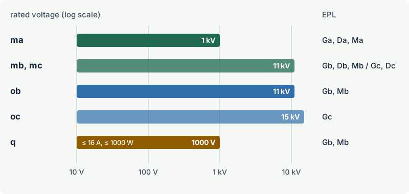
- Level ma must stay safe with two internal component faults, mb with one, and mc in normal operation; ma is limited to 1 kV, mb and mc to 11 kV under IEC 60079-18:2025.
- Liquid immersion "o" has two levels: ob (EPL Gb, Mb) up to 11 kV and oc (EPL Gc) up to 15 kV; since the 2015 edition it may protect switching contacts in AC circuits.
- In Ex o the surface temperature at the liquid surface may never exceed 200 °C, and the liquid's closed-cup flash point must be at least 25 K above the hottest liquid and component temperature.
- Powder filling "q" gives EPL Gb (or Mb) for gas only, for equipment rated at no more than 1000 V, 16 A and 1000 W; gas may enter the filling, but a flame inside is quenched by the grains.
- All three are usually sealed at manufacture: encapsulated parts are normally replaced, not repaired, and powder-filled containers are either permanently sealed or designed to be opened, refilled and resealed during repair.
Three ways of burying the ignition source
The three concepts belong to the same family as pressurisation: they separate the ignition source from the atmosphere instead of containing an explosion or limiting energy. They differ in the barrier material, and that choice decides where each one is practical.
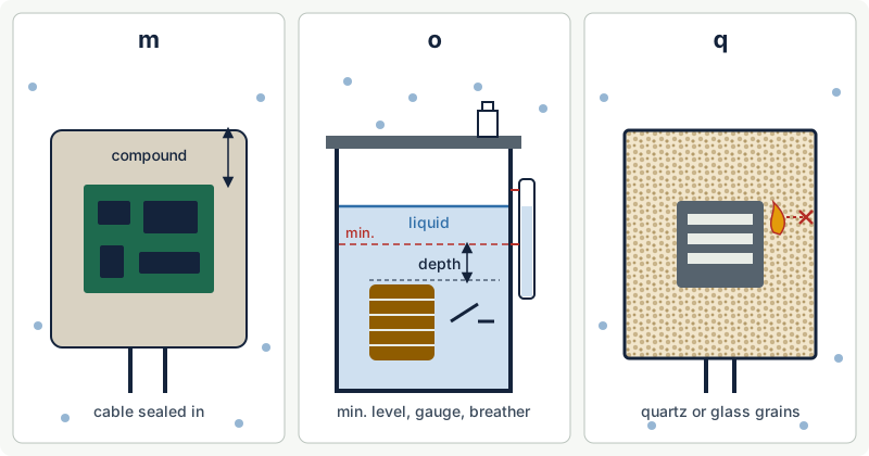
| Encapsulation "m" | Liquid immersion "o" | Powder filling "q" | |
|---|---|---|---|
| Barrier | Casting compound or other non-metallic material with adhesion | Protective liquid (mineral oil, silicone, ester) | Quartz or solid glass particles |
| Standard (current edition) | IEC 60079-18:2025 | IEC 60079-6:2015 with Amendment 1:2020 | IEC 60079-5:2015 with Amendment 1:2022 |
| Levels and EPL | ma: Ga, Da, Ma; mb: Gb, Db, Mb; mc: Gc, Dc | ob: Gb, Mb; oc: Gc | q: Gb, Mb |
| Atmospheres | Gas and dust | Gas | Gas |
| Voltage scope | ma up to 1 kV; mb, mc up to 11 kV | ob up to 11 kV; oc up to 15 kV | Up to 1000 V, 16 A, 1000 W |
| Typical uses | Solenoid coils, sensors, LED and electronic modules, small power supplies | Transformers, switching devices | Capacitors, electronic modules and ballast parts in luminaires, small transformers |
Encapsulation "m"
Principle
In encapsulation, every part that could ignite gas or dust by sparking or by heating is fully enclosed in a compound that bonds to it, so that neither an explosive atmosphere nor a dust layer can reach it. The compound is usually a thermosetting resin, but the standard also covers other non-metallic enclosures with adhesion.
Three things make encapsulation work:
- Thickness and adhesion. The compound must surround every live part with a minimum thickness and must stay bonded to components, circuit boards, terminals and any enclosure wall, so no gas path opens along a boundary. Small voids are only allowed within strict limits.
- Temperature. The compound has a specified continuous operating temperature range. Its service temperature must stay within it, both in normal operation and under the faults considered for the level, because overheated compound can crack, shrink or lose adhesion.
- Fault tolerance. Internal faults must not damage the encapsulation or produce excessive surface temperatures. Where a fault could overheat a component, a protective device such as a thermal fuse or a current-limiting element is built in or specified upstream.
Levels ma, mb and mc
| Level | EPL | Faults considered | Voltage scope |
|---|---|---|---|
| ma | Ga, Da, Ma | Up to two internal countable faults | Up to 1 kV |
| mb | Gb, Db, Mb | Up to one internal countable fault | Up to 11 kV |
| mc | Gc, Dc | Normal operation (separation distances still assessed) | Up to 11 kV |
For ma and mb, some components are treated as not failing if they are encapsulated correctly, suitable for the temperature and used at no more than two-thirds of their rated voltage, current and power: resistors, single-layer spirally wound coils, plastic film, paper and ceramic capacitors, and semiconductors. Windings that meet the increased safety requirements of IEC 60079-7 are also treated as not failing. Any other component, or one of these used above two-thirds of its ratings, is assumed to be able to fail and is included in the fault assessment.
Level ma is one of the few ways to reach EPL Ga without intrinsic safety, which is why it appears on sensors and small devices for Zone 0 and Zone 20. For dust, the maximum surface temperature of EPL Da equipment is determined with the equipment covered by a dust layer, and the marking shows the layer depth in millimetres as a subscript, for example T200 320 °C. See Ex t for how such markings are read.
What may be inside
- Switching contacts (relays, reed switches) must sit in their own housing, an arc chamber, so compound cannot enter the contact gap; level ma adds further restrictions.
- Cells and batteries must not release gas in normal operation, so vented and valve-regulated cells are excluded and gassing under fault conditions must be controlled.
- Cables are usually moulded into the compound. The free end has to be terminated in a suitably protected junction box; the encapsulation itself cannot be opened to make a connection.
Typical uses
Encapsulation suits small parts that produce some heat but no high power: solenoid valve coils, proximity switches and sensors, LED modules and drivers, small power supplies, fuses and electronic assemblies. It is also widely used inside other concepts, for example an encapsulated driver inside an increased safety luminaire, marked as a combination such as Ex eb mb IIC T4 Gb. See combined protection concepts.
Limitations
- Not repairable in practice. An encapsulated assembly is replaced as a unit when it fails.
- Heat. The compound limits how much power can be dissipated, and the certified supply conditions (rated voltage and maximum available short-circuit current) must be respected so faults stay within the compound's temperature range.
- Mechanical and chemical damage. Cracks, chips, swelling from solvents or embrittlement from UV can break the barrier.
- Certificate conditions. Many encapsulated coils carry an "X" requiring a specific upstream fuse or additional mechanical protection. See the X and U suffixes.
Liquid immersion "o"
Principle
In liquid immersion the electrical parts sit below the surface of a protective liquid, so an explosive atmosphere above the liquid or outside the enclosure cannot be ignited. Arcs and hot spots stay under the liquid, and only the liquid surface and the outer enclosure are in contact with the gas.
The concept was called oil immersion until the 2015 edition of IEC 60079-6, which renamed it liquid immersion, introduced the levels ob and oc, allowed protection of sparking contacts at both levels and added requirements for the protective liquid.
Key requirements
- Immersion depth. Live parts must stay below the minimum possible liquid level by a depth that grows with voltage and is larger for switching devices. In the 2015 edition, for example, up to 1000 V the depth is 10 mm without switching devices and 20 mm with them.
- Level indication. Each liquid-filled compartment needs a level indicator marked with the minimum and maximum levels, taking account of expansion and contraction over the ambient range. For ob equipment with switching devices, a level safety device must disconnect power automatically if the liquid falls below the minimum.
- Sealed or breathing. A sealed enclosure has a pressure relief device set to at least 10 kPa and must show visible evidence if opened. A non-sealed enclosure breathes through a device with a drying agent that needs maintenance. Breather and relief outlets face down and are at least IP66.
- Temperature. The temperature at the free surface of the liquid and on any surface the gas can reach must stay within the temperature class, and never above 200 °C. The closed-cup flash point of the liquid must be at least 25 K above the hottest liquid surface and immersed component temperature.
- Liquid. Mineral oil, silicone liquid or synthetic organic ester to the relevant IEC liquid standards, or another liquid meeting a specification that includes a fire point of at least 300 °C. Mineral oil is not acceptable for Group I (mining) equipment.
- Switching. Switching devices are permitted only in AC circuits, up to 1000 V for ob and 6.6 kV for oc. DC switching under liquid is not allowed.
- Connections. Field wiring is never protected by liquid immersion: it enters through bushings into a terminal compartment with another suitable type of protection.
Typical uses and limitations
Liquid immersion is mainly found on transformers, switching devices and similar heavy electrical equipment, where liquid already serves for insulation and cooling. It is rare on small equipment.
Its limits follow from the liquid. The equipment must be installed in the orientation the manufacturer specifies, the level and the drying agent need regular checks, leaks remove the protection, and the liquid adds a fire load. Ex o is a gas-only concept and gives no dust EPL.
Powder filling "q"
Principle
In powder filling, the parts that could cause ignition are fixed in position and completely surrounded by a filling of quartz or solid glass particles. Unlike encapsulation, the filling does not keep the gas out: gas can seep into the voids between grains and could even be ignited inside. But the voids are so small, and the paths through the filling so long and narrow, that any flame is cooled and quenched before it reaches the outside.
Key requirements
- Filling material. Quartz or solid glass particles graded between nominal sieve apertures of 1 mm and 500 µm, filled without voids (for example by vibrating the container).
- Distances. Minimum distances through the filling between live parts and the container grow with voltage; in the 2015 edition, for example, 5 mm up to 250 V and 14 mm at 1000 V.
- Container. At least IP54 (IP43 only for clean, dry rooms, with an "X" on the certificate). Any gap must be at least 0.1 mm smaller than the smallest particle so the filling cannot leak out.
- Components. A component with an enclosed free space, such as a relay, may have at most 30 cm³ of free volume, with extra filling around it. The total energy stored in all capacitors must not exceed 20 J in normal operation.
- Sealing. Containers are filled and sealed at manufacture, either permanently (opening leaves visible evidence) or designed to be opened for repair, refilled and resealed. Cables entering a powder-filled container are an integral part of the equipment.
Typical uses and limitations
Powder filling is used for compact parts that may spark or get hot in fault conditions: capacitors, electronic ballast and driver components in luminaires, small transformers, fuses, electronic modules and associated apparatus for intrinsically safe circuits. As an Ex component it is often mounted inside another enclosure, typically an increased safety one.
The limits are clear: gas only, EPL Gb at most, rated supply of no more than 1000 V, 16 A and 1000 W, and no access to the inside in the field. If a powder-filled part is damaged or the filling leaks, it is replaced.
How to choose between them
| Question | m | o | q |
|---|---|---|---|
| Zone 0 or Zone 20 needed? | Yes, with ma | No | No |
| Dust area? | Yes | No | No |
| Sparking contacts inside? | Only in their own sealed housing | Yes, AC only, within voltage limits | Yes, within the filling rules |
| High power or high voltage? | Limited by heat in the compound | Suitable up to 11 or 15 kV | No: 1000 V, 16 A, 1000 W |
| Field repair possible? | No, replace | Liquid top-up and maintenance | Only resealable designs, by competent repairers |
| Main inspection points | Cracks, discoloration, cable entry | Level, leaks, drying agent, relief device | Container intact, seals, no leaking filling |
In practice, the choice is often made by the manufacturer of a product that combines concepts: an increased safety luminaire with an encapsulated driver and a powder-filled capacitor, or a motor terminal box with an encapsulated sensor. The user's job is to check that the overall marking and EPL suit the zone, gas group and temperature class.
Practical case: a solenoid valve coil on a Zone 1 skid
A valve on a solvent skid in Zone 1, gas group IIB, temperature class T4, needs a solenoid coil. A coil marked Ex mb IIC T4 Gb is suitable: mb gives EPL Gb, IIC covers IIB, and T4 matches the requirement. If the same skid sits where combustible dust is present, the coil also needs a dust marking such as Ex mb IIIC T130 °C Db, and its maximum surface temperature must suit the dust (see surface temperature limits for dust).
Then check the details that are easy to miss:
- Supply. The certificate states the rated voltage range; a 24 V DC coil fed at 28 V may run hotter than its temperature class allows.
- Upstream fuse. Many encapsulated coils carry an "X" requiring a fuse of a given rating and breaking capacity in the supply, to protect the compound in a winding fault.
- Cable termination. The moulded cable must end in a junction box suitable for Zone 1, such as an
Ex ebbox with a certified gland. - Duty and ambient. Continuous energisation at the top of the ambient range is the hottest case; check it against the certified ambient temperature range.
Common mistakes
- Cutting into an encapsulated part to shorten a cable or replace a component. Any break in the compound destroys the protection; replace the part.
- Assuming Ex q or Ex o covers dust. Both are gas-only concepts; dust areas need Ex m, Ex t, Ex i or Ex p equipment marked for Group III.
- Ignoring the liquid level. An Ex o device with low liquid is not protected; level and drying agent are routine inspection items under IEC 60079-17.
- Installing liquid-filled equipment in the wrong orientation, which can leave live parts closer to the surface than the certified depth.
- Overlooking X conditions such as upstream fuses, maximum prospective short-circuit current or mechanical protection for encapsulated parts.
- Treating "m" on a component as a rating for the whole product. The EPL of combined equipment is set by its weakest concept.
Frequently asked questions
What is the difference between Ex m and Ex q?
Both surround the ignition source with a material. In Ex m the compound bonds to the parts and keeps the atmosphere out completely. In Ex q the grains let gas in but quench any flame before it can leave the container. Ex m covers gas and dust and reaches EPL Ga; Ex q is for gas only and gives EPL Gb.
Can encapsulated equipment be used in Zone 0?
Yes, if it is level ma, which gives EPL Ga (and Da for Zone 20). Level ma must stay safe with two internal faults and is limited to 1 kV. Levels mb and mc give EPL Gb and Gc and are for Zone 1 and Zone 2.
Why is oil immersion now called liquid immersion?
The 2015 edition of IEC 60079-6 broadened the concept beyond mineral oil to silicone liquids, synthetic esters and other liquids that meet a defined specification. It also introduced the levels ob and oc and allowed switching contacts to be protected by immersion.
Is Ex o still used today?
Yes, but mainly for transformers and switching devices, where a liquid already provides insulation and cooling. For small equipment, encapsulation, powder filling or increased safety are usually more practical.
Can Ex m or Ex q equipment be repaired?
Encapsulated parts are normally replaced, because the compound cannot be reopened without destroying the protection. Powder-filled containers designed to be opened for repair can be refilled and resealed, but only following the manufacturer's procedure and the repair rules of IEC 60079-19. See repair, overhaul and modification.
Related on excodex
- Ex protection concepts at a glance
- Pressurisation (Ex p)
- Increased safety (Ex e)
- Equipment Protection Levels (EPL)
- Combined protection concepts
- Tools: Ex marking check, forum, standards spaces IEC 60079-18, IEC 60079-6 and IEC 60079-5
Standards and further reading
- IEC 60079-18, equipment protection by encapsulation "m" (edition 5, 2025).
- IEC 60079-6, equipment protection by liquid immersion "o" (2015 with Amendment 1 of 2020).
- IEC 60079-5, equipment protection by powder filling "q" (2015 with Amendment 1 of 2022).
- IEC 60079-0, general requirements; IEC 60079-14, installation; IEC 60079-17, inspection; IEC 60079-19, repair.
- IEC 60079-18:2025 scope and levels, standards database entry: scc-ccn.ca
- IEC 60079-6 consolidated edition, abstract: webstore.iec.ch
- IEC 60079-6:2015 text, incorporated by reference in US federal regulations: law.resource.org; IEC webstore (current edition, IEC 60079-6:2015+AMD1:2020): webstore.iec.ch
- IEC 60079-5:2015 text: law.resource.org; IEC webstore (current edition, IEC 60079-5:2015+AMD1:2022): webstore.iec.ch
- IEC 60079-18:2014 with Amendment 1:2017 text (previous edition): law.resource.org; IEC webstore (current edition, IEC 60079-18:2025): webstore.iec.ch
This article is general technical information prepared by the excodex editorial team. It does not replace the applicable standards, the equipment certificates and instructions, national regulations or the assessment of a competent person.